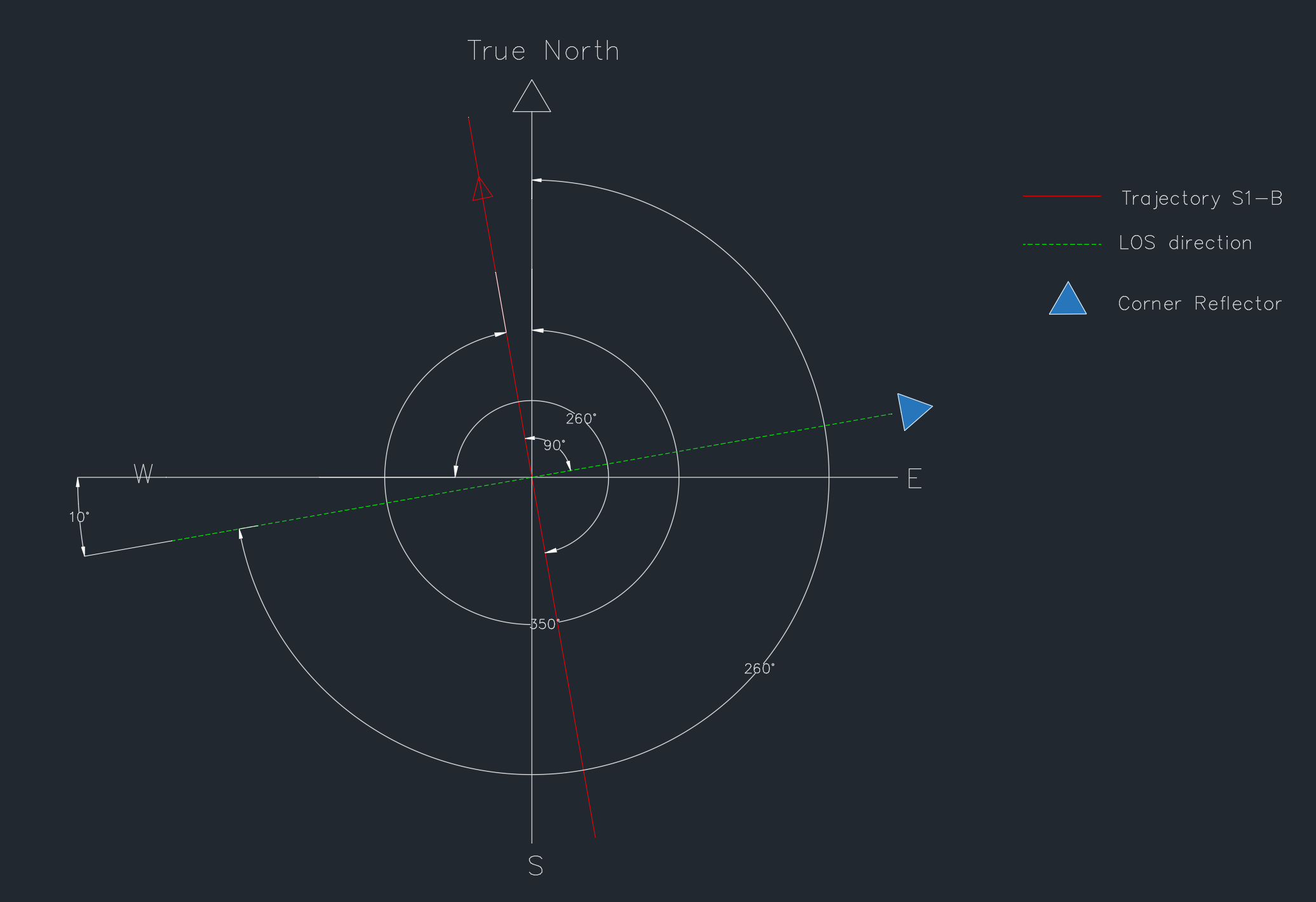
I’m a little confused. if I draw azimuth 260° referred to true north, the trajectory isn’t corresponding with the map and kml file such as you can see in the next image
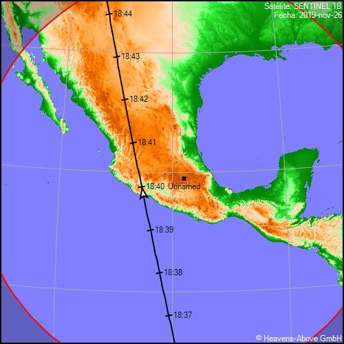
This is the terrestrial trajectory for sentinel 1-B, ascendent orbit and antenna looks to the right side on November 26.
I believe the azimuth isn’t the trajectory for sentinel 1-B, if I orientate from true north the direction is perpendicular to the trajectory that you can see on the terrestrial trajectory map and CAD image.
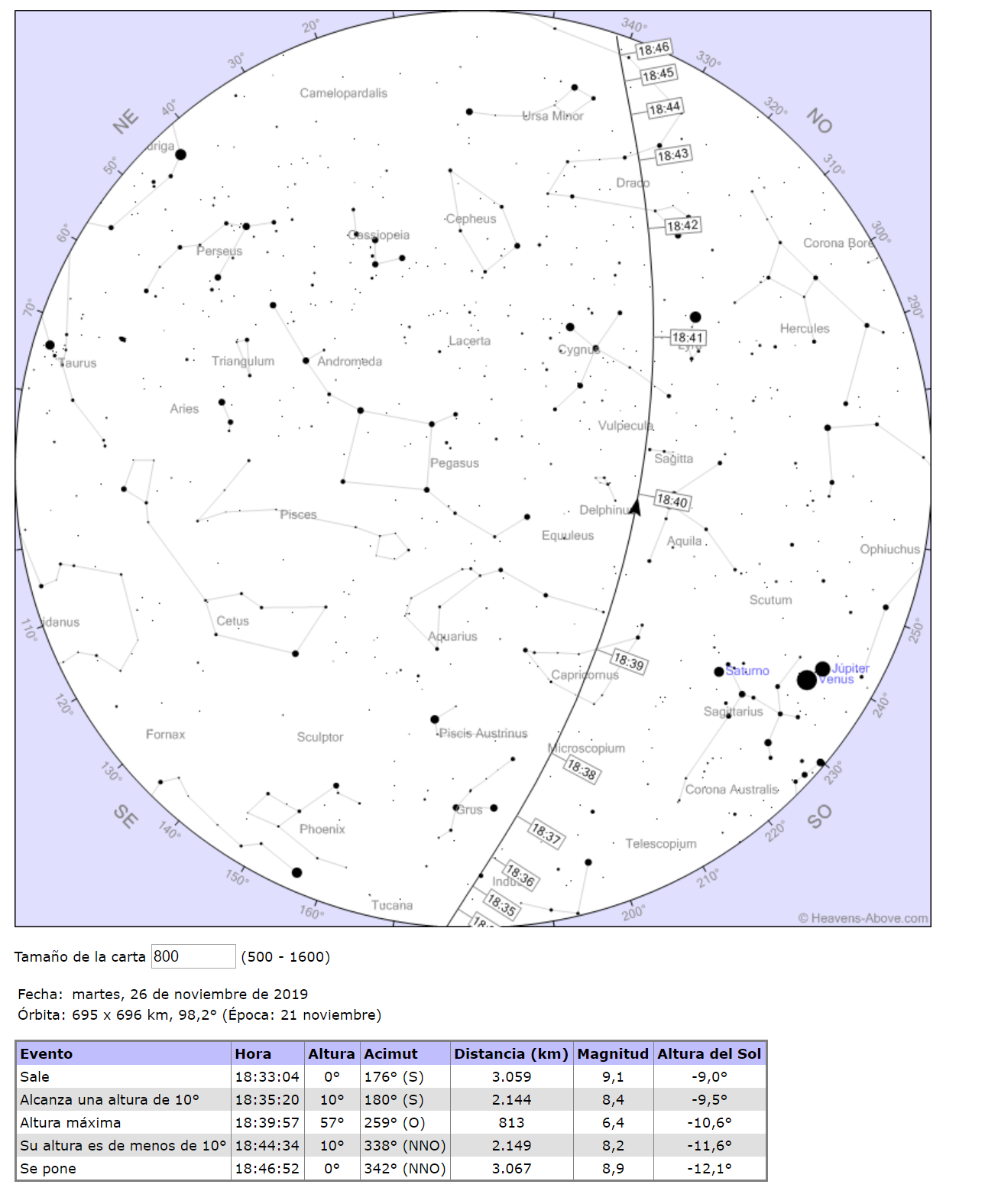
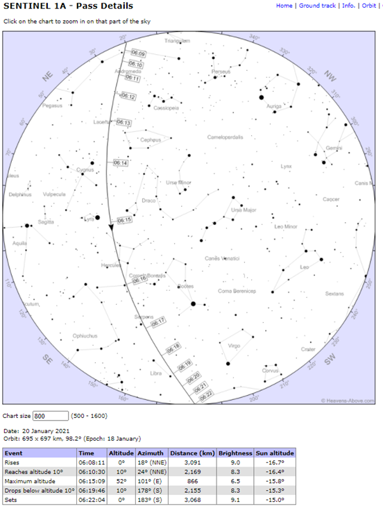
Hi @CFEgildan71, I think the confusion is because there are two different azimuth angles: (i) the angle given in Heavens-Above (HA) and (ii) the S1 path azimuth angle.
The HA website is mainly for amatur astronomer who want to know when and where in the sky to observe a satellite. So HA gives the azimuth and elevation angles of a satellite for an observer on the ground. In your case the location on the ground is where your CR is located and the azimuth angle is relative to true north and is used to orientate your CR (along with the elevation angle). To be more specific the azimuth and elevation angles at maximum alitude are used (for the 26th, the azimuth is 259 deg and altitude of 57 deg or 57-35 = 22 deg for the base of the CR). Note that the sky map has east to the left and west to the right.
The other azimuth angle that you mention is for the trajectory of S1 as shown in your first map of Mexico. This angle is not related to the orientation of your CR. All you need to make sure is that the planned swath includes the location of your CR (as is the case shown in your last map for the S1-B pass on 27th Nov at 00:39 UT).
You’re right, the angle given in Heaven Above is for observing satellite from a position on the ground and it’s perpendicular to the trajectory of sentinel-1. If you add or extract 90 degrees (it depends to orbit direction) to Heaven’s angle, can get the theoretical trajectory of sentinel-1. I confused the theoretical trajectory of sentinel with Heaven’s angle.
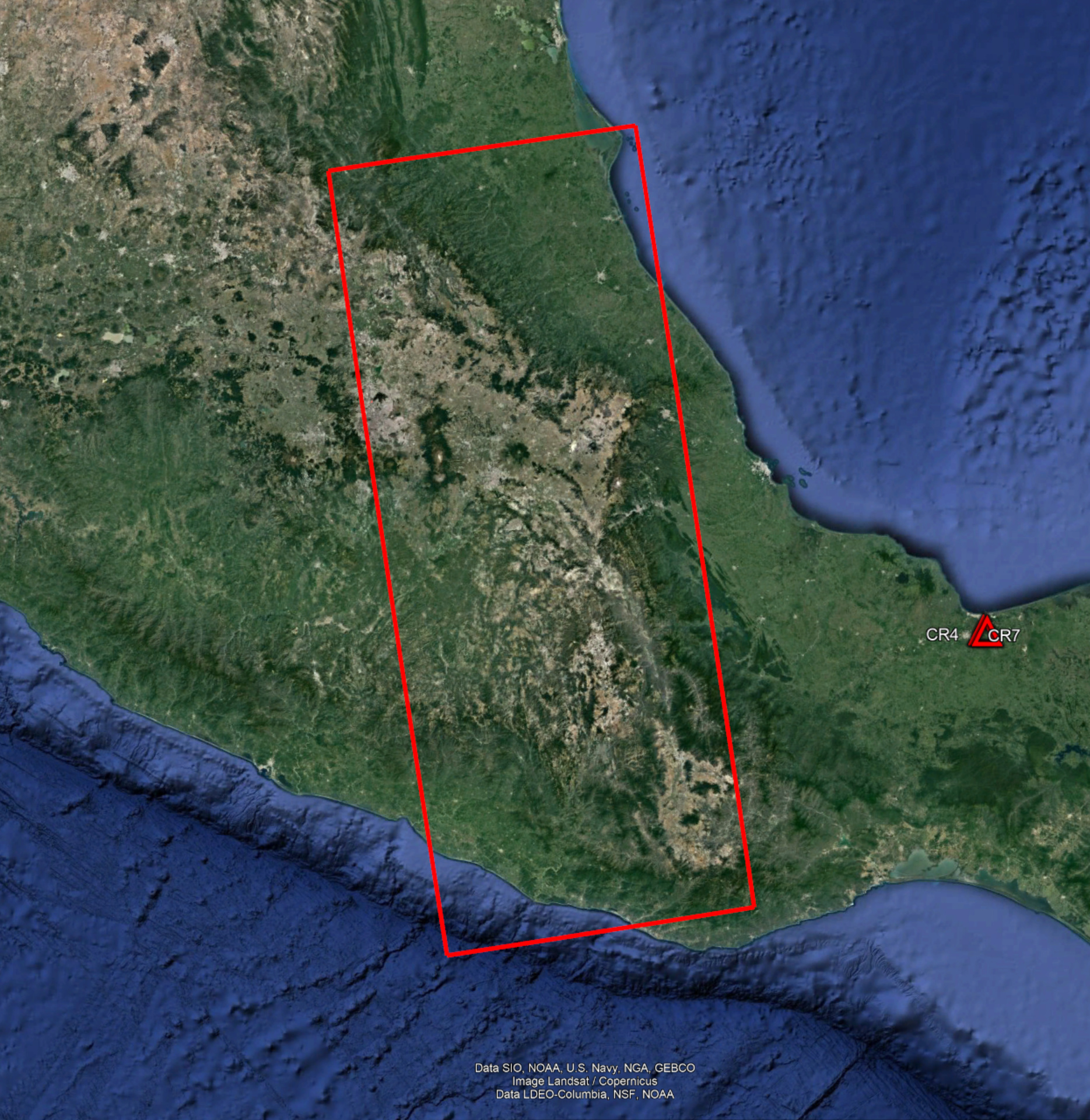
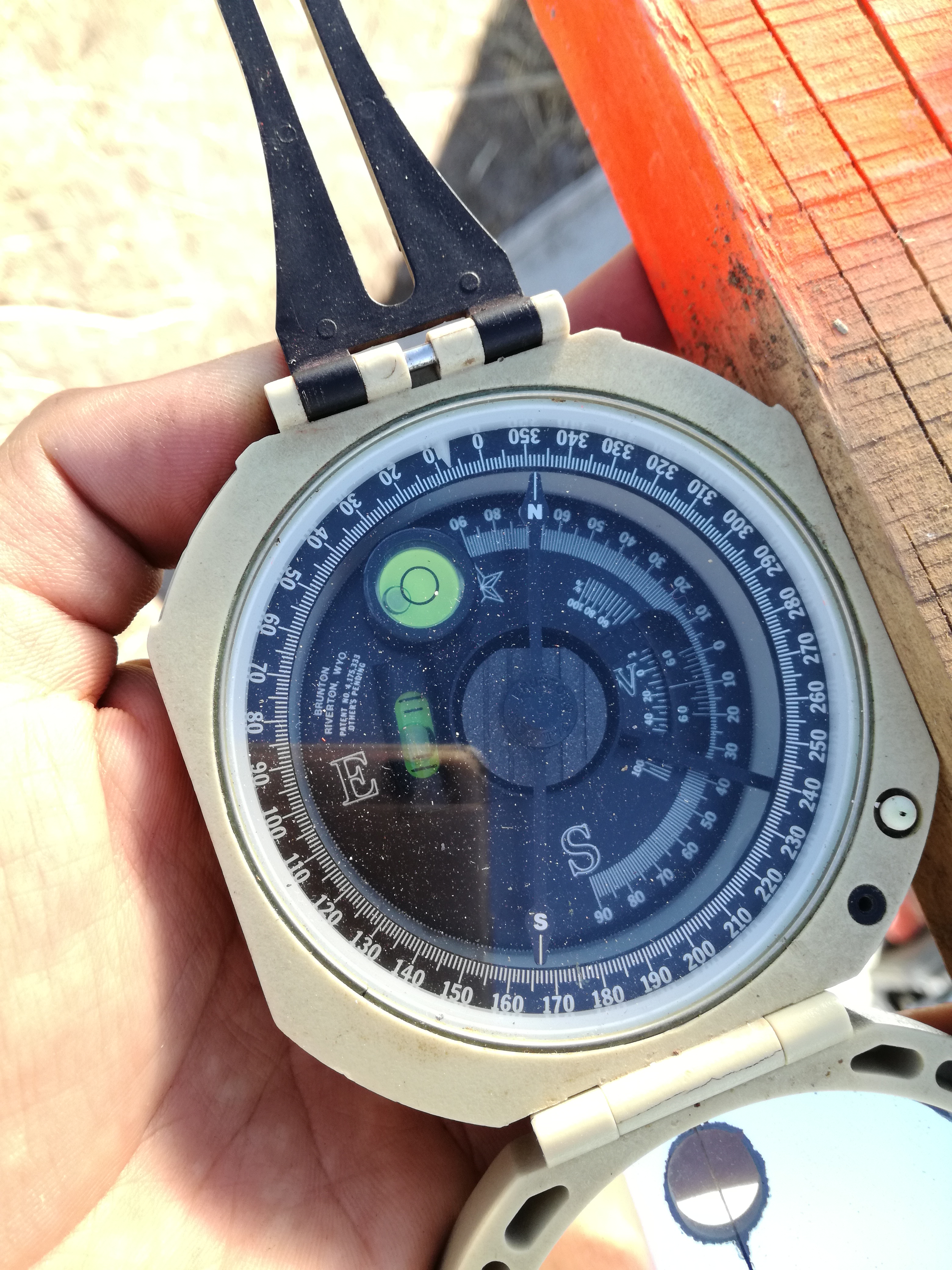
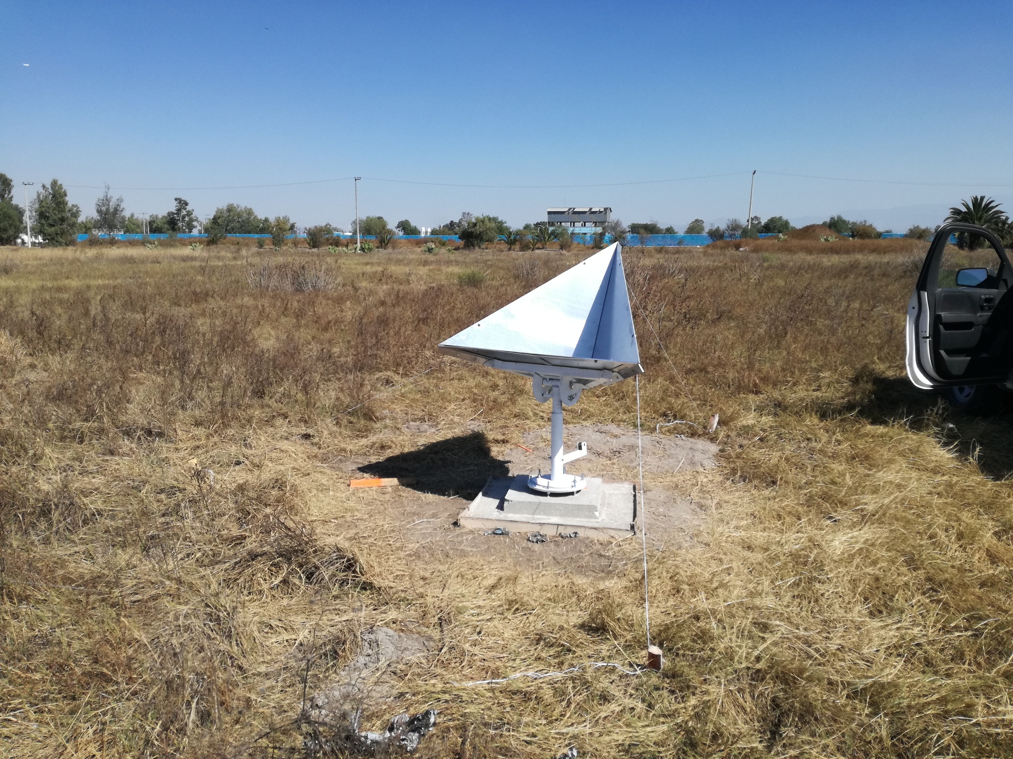
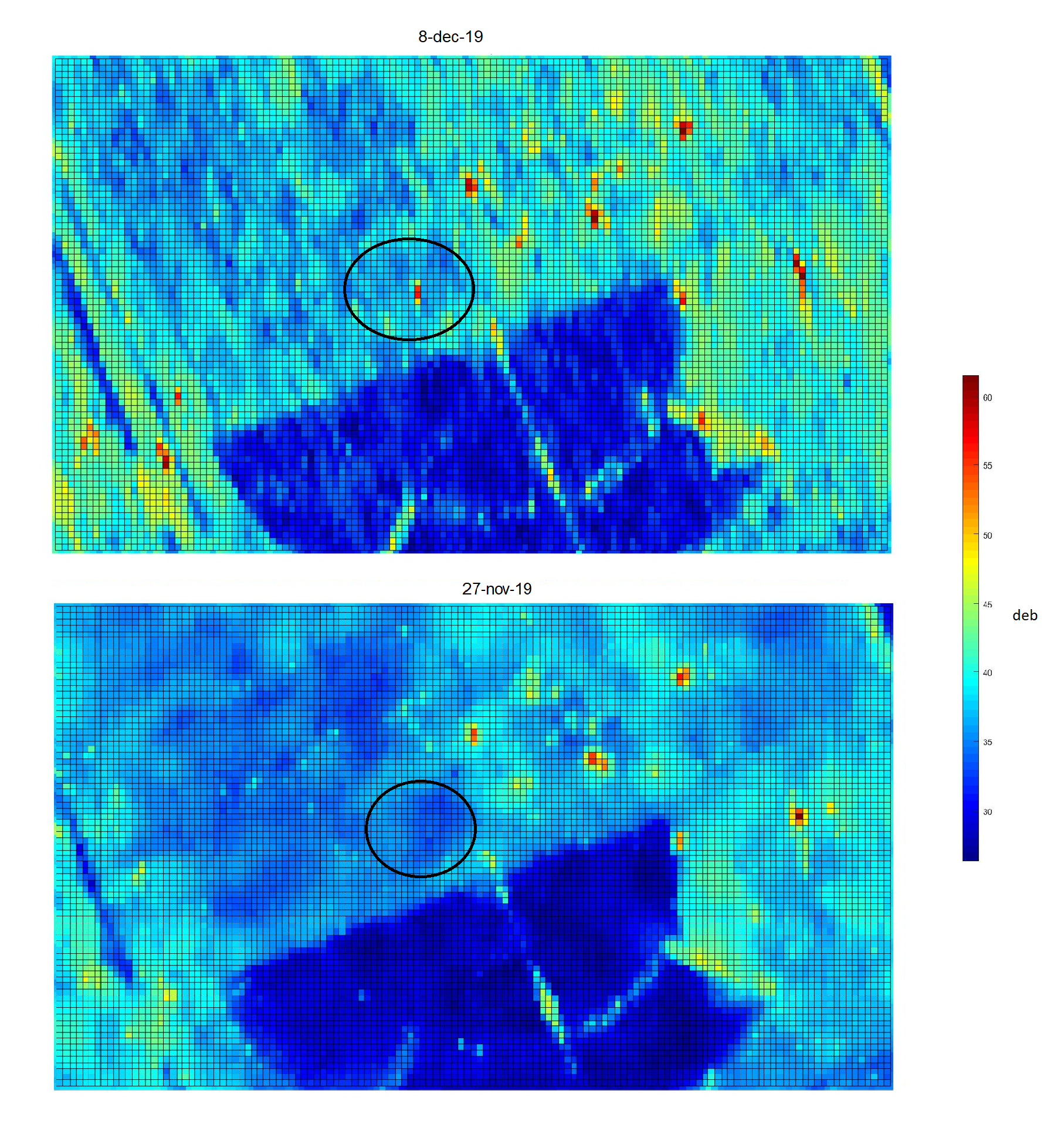
This is my 1m corner reflector identification on the surface. I oriented it using a Brunton compass, I had a few problems with the magnetic camp produced by the corner reflector, Brunton compass its very sensitive if I put it on the reflector. I oriented it using Heaven Above data and kml programming of ESA.
Hi @CFEgildan71, I have some question about your CR analysis. To find CR in Sentinel images, did you use SLC or GRD data? And, what preprocessing steps on SNAP did you apply? Thanks in advance.
I’m sorry for the late response. I used SLC, the main objective to install CR on the ground is to get accurate measurements at a specific point, and for that, you need SLC imagery that contains amplitude and phase information.
You can use the coherence information and the coordinate that you should be taken when installing the CR, remember, the backscatter and coherence of your corner reflector should be higher than the environment. Once you have found your CR, you can calculate the cross-section.
Dear Peter
Thank you for useful information for CR orientation. I have the same question as @manconia. I have followed your instructions and found the azimuth and elevation (found elevation 52 and base angle 52-35=17 and azimuth 101 (for our 1-m size and trihedral shape) from HA for Descending orbit and the location of CR is in Sweden at 17.2588, 60.5946. It seems that the CR is not visible in GRD image when I look at EO browser. My question is why we are finding the elevation from HA and not from incidence angle of S1 for that specific location? The incidence angle for example is 43 degrees and this means 90-43=47 degrees which is different from 52 which HA gives us. In some papers also use incidence angle for calculation of base angle. Would you please help?
Thanks.
You are correct in saying that either the elevation angle or incidence angle can be used to orientate your CR in elevation. Using either parameter should give the same orientation. I’ve checked the incidence angle (from the product) and elevation (from HA) for the BAE CR (2.5m trihedral) as shown below for S1-A in January 2019:
Acq Date
Cycle
Orbit
Rel Orbit
Product
Site
Inc Angle (°)
CR Elev (°)
Total
04/01/2019
159
25331
59
SLC
BAE
33.61
56
89.61
09/01/2019
159
25404
132
SLC
BAE
42.16
48
90.16
16/01/2019
160
25506
59
SLC
BAE
33.62
56
89.62
18/01/2019
160
25528
81
SLC
BAE
35.14
55
90.14
21/01/2019
160
25579
132
SLC
BAE
42.16
48
90.16
28/01/2019
161
25681
59
SLC
BAE
33.62
56
89.62
As you will see, the sum of the incidence angle and the elevation angle is very close to 90deg as expected. Remember, the incidence angle is this angle at the location of the CR and it has to be calculated for the actual peak pixel coordinate of the CR - this may only be known after receiving the product, hence the reason for using HA for planning. I suggest checking the calculation of the incidence angle value you give (43 deg).
For your 1m CR have you thought of looking at the SLC product? It should be easier to see in the SLC compared to the GRD given the finer pixel size of the SLC product.
Hi Peter
Thank you for confirmation and useful info. I looked at my GRD image in SNAP again and zoomed on the Pixel which I know its coordinates (planned location of the CR) and I found the incidence angle of 37.67 degrees. I’m afraid, I did mistake in the first try, and I thought it was 43 degrees. You are right and now similar to what you showed in the table, the sum for me is also close to 90. Or if I do 90-37,67=52,33 which is close to HA value (52 degrees).
So this means another way to find the elavation angle is: Open a GRD image, look at the Tie-point-grids, find the incidence angle for the CR location and then subtract from 90 degrees and then subtract by 35.26 (trihedral). This way, we can find the tilt angle of the base plate of the CR. Now it is clear for me.
As you suggested, I will also check it in SLC image later.
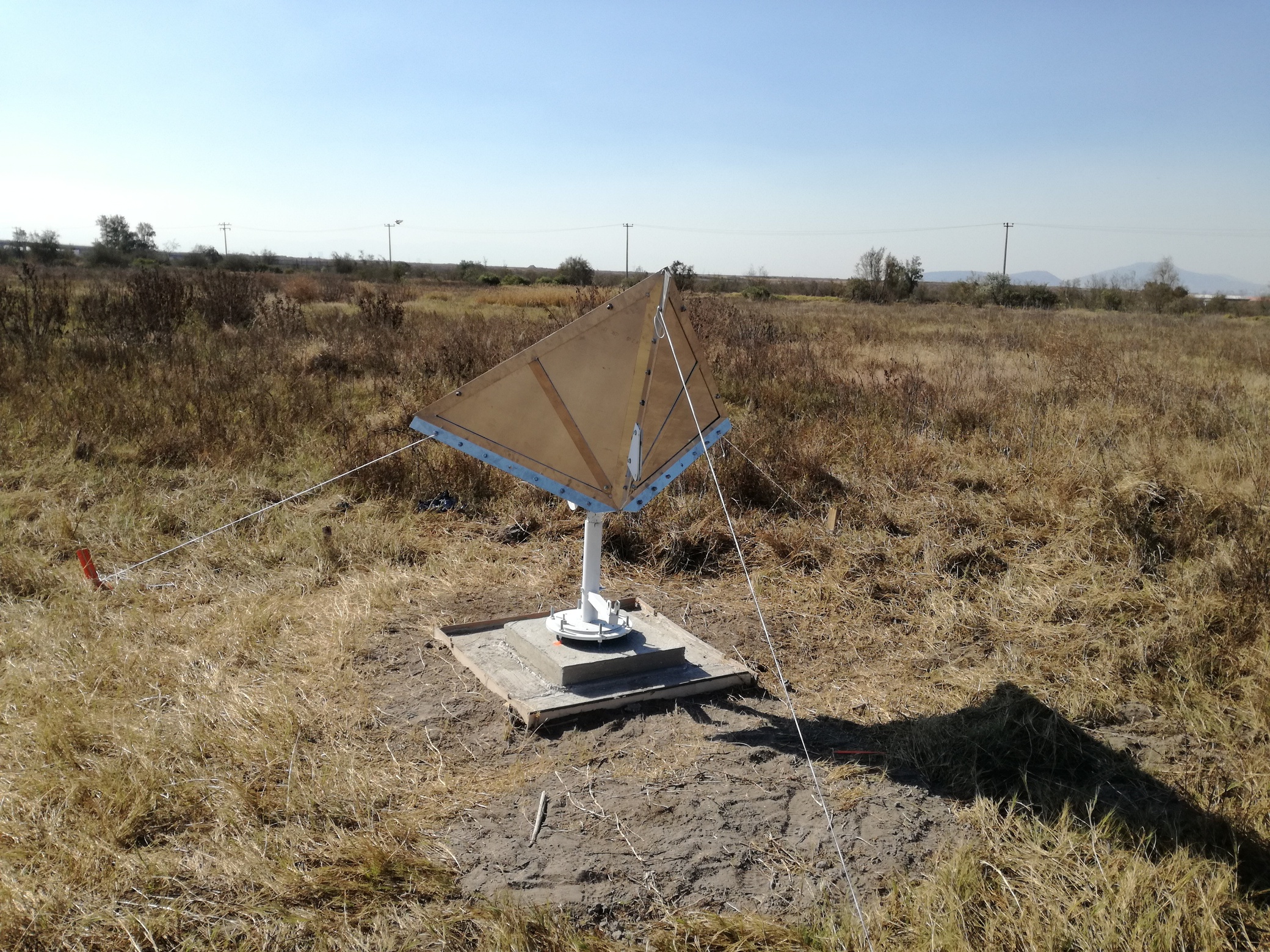
Yesterday I tried to install a temporary CR (triangular shape, perforated and 955 mm side length) using your same way of positioning and now I’m waiting the updating of Sentinel data to find out if the satellite has seen it.
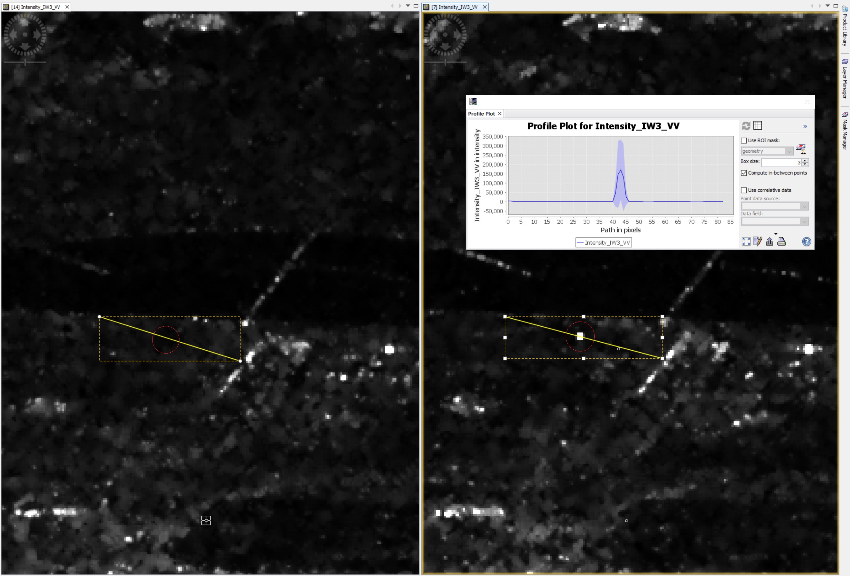
So I’m curious to know if your CR is visible on SLC data, because I can’t see your CR on GRD using EO browser at your coordinates.
Hi @Giova, thanks, you may noticed that there is a strong signal coming from transponder (active corner reflector) just NW of the the CR (1m) and that seems to make it a bit difficult to find the CR in EO (side effect?), but still I see a small signature of the CR in EO. However, I tried the GRD in SNAP (and I would suggest you to do so for this CR if interested or for yours), calibrated and calculated the Beta0_db and by using RCS=10 x log(Beta0_db x 10m x 10m), I got something between 22-24 dbm2 for our CR in different days. This is weaker than ~30-32 dbm2 for 1-m size CR which we expected (theoretical value), but this is a temporary installation on a wooden palett (just for test and we may move it to a better place), and not sure if it has been stable after we have left it. Will check the orientation in the field again. Good to see how yours (similar CR shape and size) is working. Good luck.
Hi, all corner reflectors are made of metal but can be in different forms depending on their size and operating frequency/wavelength. For a small CR, say 1-2 m, the a solid sheet of metal can be used for the three sides. If you want to reduce the weight of the CR, a metal sheet with perforated holes can be used provided the hole diameter is < 10% of the wavelength. So for C-band the holes need to be ~0.5cm or less. For larger CR that operate at low frequency (e.g. L band), a mesh can be used.
I suggest you do a Internet search for SAR Corner Reflectors and look at the images found.
Can you present me an article where it talks about the dimensions of the CR?
FOR ECONOMIC REASONS I CAN MAKE A CR IN WOOD COVERED WITH ALUMINUM SHEETS (tinfoil) ?
Thanks @peter.meadows
I would suggest the minimum size of a CR would be a = 1m. Although I’m sure you could make the CR frame for wood, the three surfaces of the CR need to be quite flat especially of you want to do measurements using the CR (position or radar cross-section). A thin sheet of metal would be much better than tinfoil as this is not particularly flat.