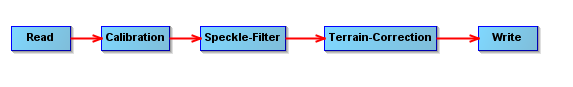
I am currently using a number of TerraSAR X images captured in Spotlight mode in order to measure building dimensions. However I am getting incorrect measurements for the buildings, they are correct in length but nearly double their width, the error seems to in the range direction. The images below show the graph I used to process the scene and the result, it looks very blurry still is there any recommendations for processing this type of data to try and help the image quality and possible correction for the building dimension errors.
Did you consider multi-looking after calibration instead of speckle filtering?
I had better results with that (at least with Staring Spotlight products which you probably also use)
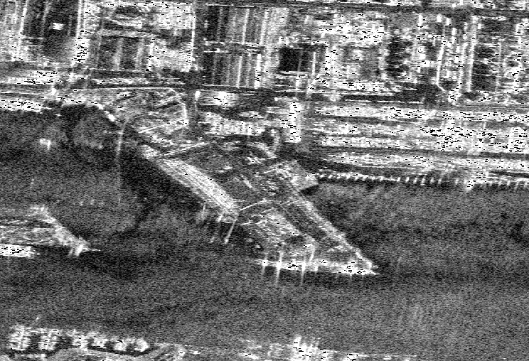
Thank you for the quick reply @ABraun, I tried doing a multi-looking instead and the result is shown below which does appear a lot cleaner. For the geometric correction, is the Range Doppler Terrain Correction the best method to correct for TerraSAR X in Spotlight or are all the terrain correction options equally as good?
Darragh
yes, Range Doppler Terrain Correction is the standard procedure. Its quality however depends on the input DEM so if you have anything better thant SRTM 1ArcSec (Auto Download) that would surely help.
Ok perfect thank you very much! I have about 4-5 of these Spotlight images, it is possible to carry out a multi-temporal filter to improve the image more or would this required 10+ images?
You could try coregistering the scenes after multilooking and apply the multi-temporal filter but I’m afraid they are too few for the filter being effective. But would be worth a try.
Use of 4-5 images in a multitemporal filter would already help quite a bit I think. If I’m not mistaken the speckle standard deviation goes down with 1/sqrt(N) so if you have four images speckle is ideally reduced by 50% in the average image. The multitemporal filter is less effective but still the improvement should be clear. Please try it and report back!
As for the geometric errors, have you tried to open the terrain corrected image on Google Earth? Do flat areas (i.e. not buildings) match with Google’s imagery? If they do, you are doing something wrong with your building measurement. If they don’t, there is a problem with SNAP/the image/the processing.
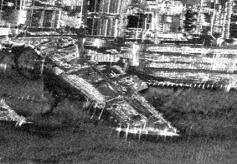
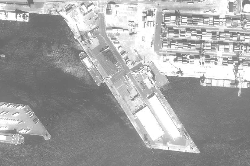
Out of curiosity: do you know what the object below is? It looks like a passenger ship but distorted in a strange way (not straight but without azimuth smearing). I’d assume that distortion has been introduced by the terrain correction step.
I have just reviewed the previous acquisitions we had for TerraSAR X and our current ones @ABraun@mengdahl, and I have noticed that we changed the parameters of the acquisitions. The first two or three images had a low incidence angle , while subsequent images had an adjusted higher angle to 45° to improve the range resolution to 0.85m. Is it still possible to use a multi-temporal filter on this data or will the change in angle effect this too much?
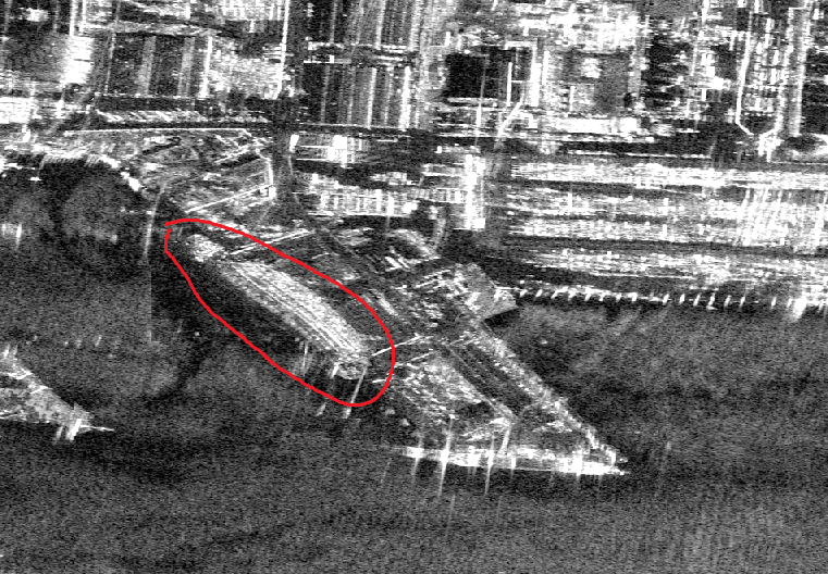
As for the geometric issue @css, I opened the image in google maps and the flat areas to appear to match relatively well with the Google imagery, I have no managed to get a building measurements much closer to their actual size (within about 2m). The object does appear to be a ship, as shown in the pleiades tri stereo image captured around the same time. The distortion must be introduced by the terrain correction
if the incidence angles differ too largely you inevitably get Pixels with contain different objects in the SAR image, especially in urban areas. So while one pixel represents a house in a large incidence angle it could as well be no longer a house in a small incidence angle image. Try to overlay both images and visually compare to get an impression on the effects of the different angles.
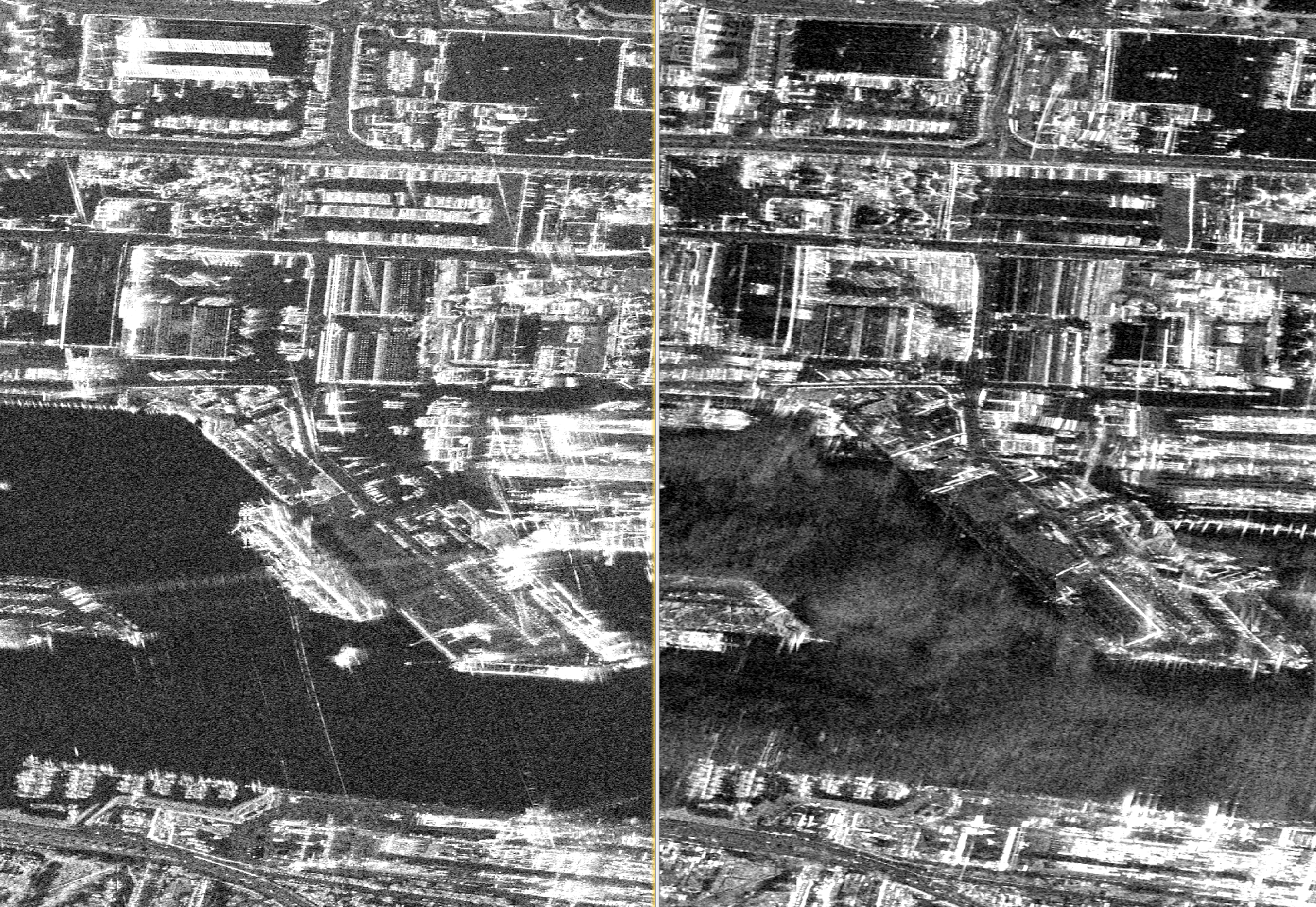
The first 3 acquisitions were captured with an incidence angle of 25.71°, and two subsequent images with the new altered angles of 42.14°. The image below shows how the images look at the different angles, left is the new angle of 42° and right is the old 25°.
It seems that one of those images was acquired during an ascending orbit and the other one during a descending orbit. Assuming they are both right looking, what you effectively see is different sides of the same buildings.
Note that a DTM can only be used to correct for terrain. It lacks building height. A DSM would be more meaningful or no DEM correction at all in order not to distort the image.
Also note, that you had a tall ship in your image with many floors. The layover perfectly shows this.
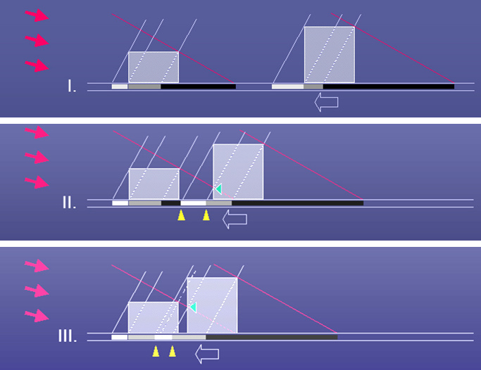
In the SpotLight image you will notice geometric effects and object misplacement even more than in StripMap data. Note that building shadows can be “eaten up” by the layover of adjacent buildings. Also, the top of the building is not always fully shown. (white = front, grey = roof, black = shadow) Note the strong dependency on the applied incidence angle.