My ultimate goal is to have a calibrated, terrain flattened, terrain corrected, projected sigma0 image in dB. I am starting with S1A EW mode medium resolution GRD data (S1A_EW_GRDM…).
Here is my workflow in S1TBX (tried beta 7 and 8, also 1.1.1):
Calibration
Terrain Flattening using external DEM (gives gamma0 images)
(Range Doppler) Terrain Correction using same external DEM and projecting to UTM (gives gamma0, elevation, lat, lon, localIncidenceAngle, projectedIncidenceAngle, incidenceAngleFromEllipsoid)
Convert gamma0 to gamma0 in dB
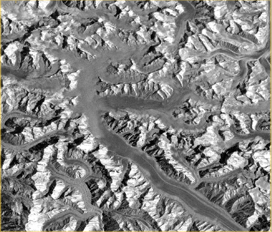
Everything in steps 1-4 looks OK as far as I can tell (the TF and TC seem to have done their jobs).
But, I need to get sigma0 values in dB so I apply some band math, assuming:
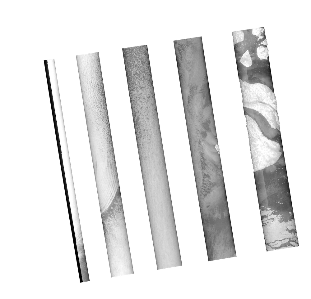
σ0 (dB) = γ0 (dB) + 10 * log10(cos(incidence_angle))
Which gives me (I am using the incidenceAngleFromEllipsoid) an image with banding:
The white bands above seem to be set to NaN. It’s weird, because my incidence angle image doesn’t appear to contain anything that would cause this banding. Is my math incorrect, or is this a bug? Is there a better way to get the sigma0 I want (post TC and TF)?
Had not issues trying the proposed chain using SRTM DEM (auto download).
Could you try it with SRTM as well to check if the problem is coming from the external DEM?
Please consider applying and update of the orbit state vectors to ensure optimum geocoding results. I would also leave TC at the end after all processing conversions are done.
That was the problem! I converted to radians and no banding was produced and the image looks good.
Now I think my question is if I need to convert to sigma naught, or should I just use gamma naught instead? I’m accustomed to using sigma0, so I guess I need to do some more reading.
I have been doing a similar process with S1A SLC IW imagery. My workflow is as follows:
-Deburst
-Remove Thermal Noise
-Orbital Correction
-Calibrate to Beta0
-Speckle Reduction
-Multilook
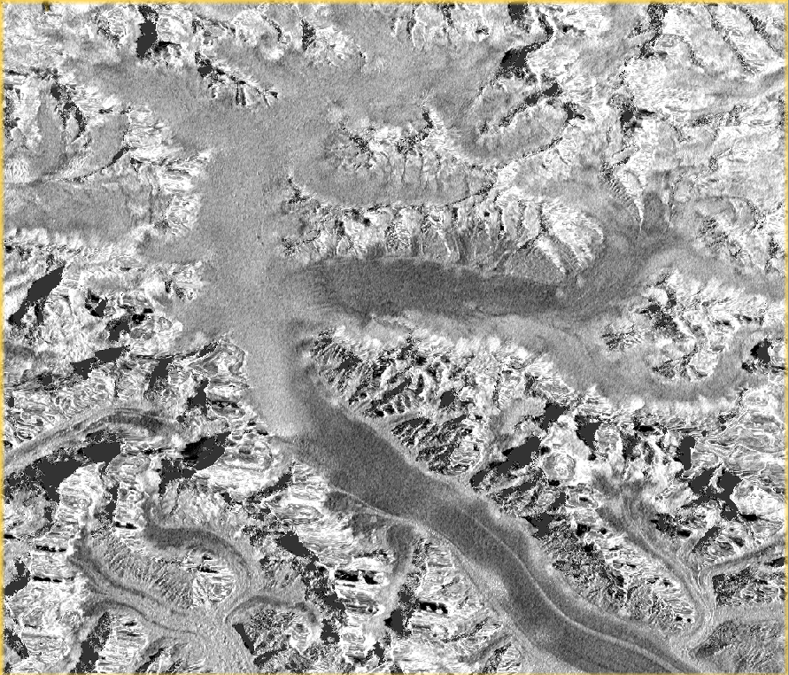
-Terrain Flatten to obtain Gamma0
-Terrain Correct (Range Doppler using SRTM 1 sec HGT)
-Using band math on Gamma0 to determine Sigma0
The results show images that appear much more speckled than ignoring skipping terrain flattening altogether, and simply Terrain Correcting and applying radiometric normalization (everything else the same). Anyone know why this might be?
The algorithm is the same in principle but the current implementation in SNAP has some issues that could be related to DEM-sampling. @junlu could you comment?
This refers to version 2. Improvements have been done since then.
Here are some of the test results we did a few months ago. Terrain Flattening Test.pdf (846.4 KB)