Hi, ABraun!
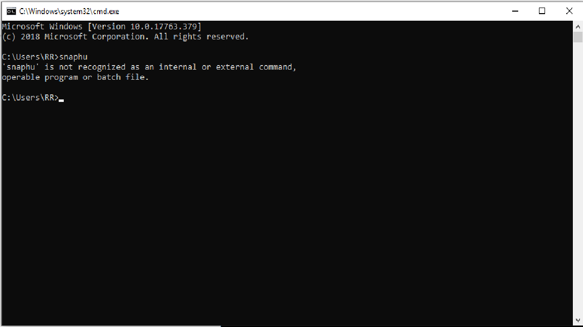
I just to ask how do I solve this problem? I want to do phase unwrapping using SNAPHU but I am encountering this problem. I hope you can help me.
Thank you.
Hi, ABraun!
I just to ask how do I solve this problem? I want to do phase unwrapping using SNAPHU but I am encountering this problem. I hope you can help me.
Thank you.
Hi, falahfakhri!
Thank you! Yes. I just realized that actually. So this means I can work now with the phase unwrapping using SNAPHU, right? I am a beginner actually and following a training through webinar. I am finished with the InSAR processing now and I hope to execute properly the phase unwrapping.
Thank you again.
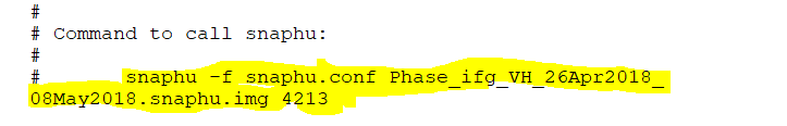
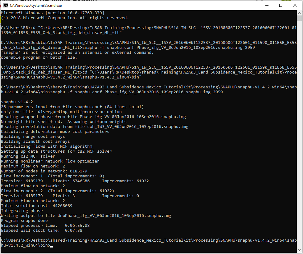
Yes, you could do it in two ways, after export snaphu you could run the script by copying it and paste in your terminal, the script is existed within snaphu.conf,
And run it, later on, import snaphu,
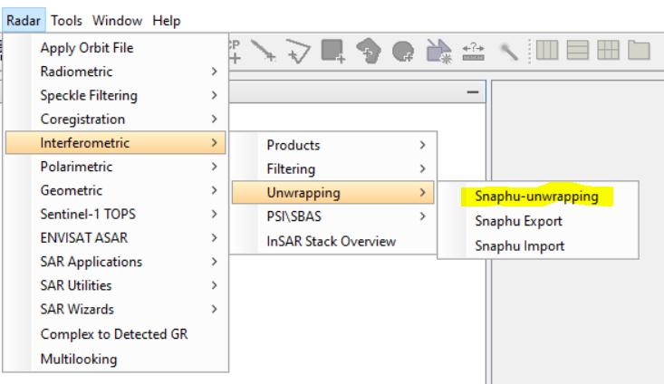
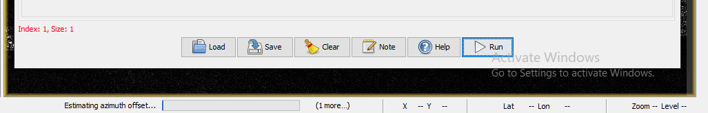
Or your could do in this way using only SNAP, first export snaphu and then Snaphu unwrapping
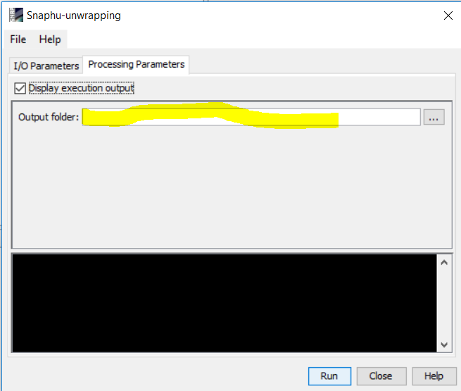
Check the box to see the function running and add the path of your folder by copy and paste it,
Then import snaphu
Hi, falahfakhri!
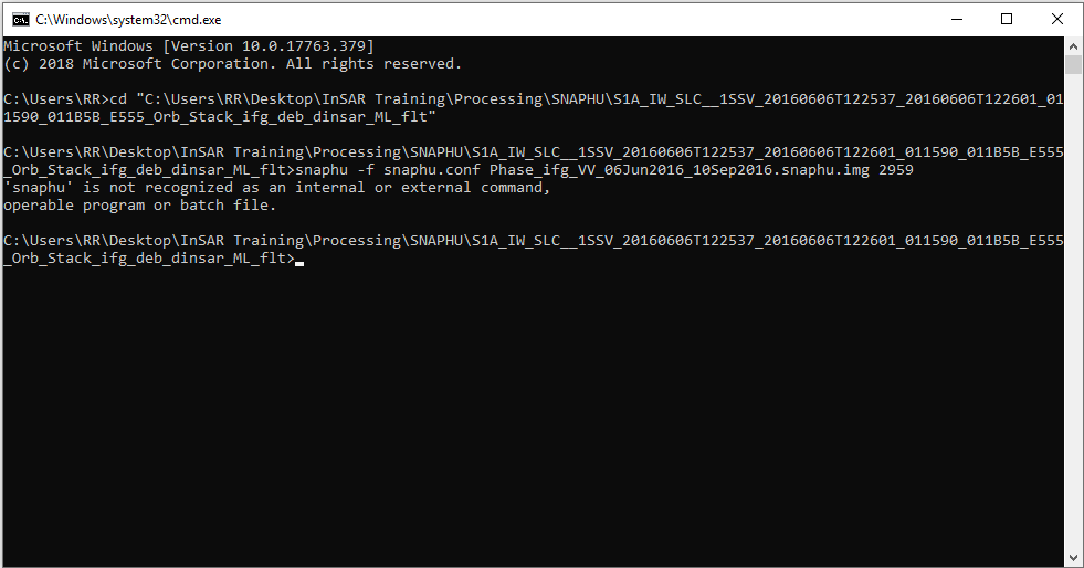
I have another problem. Could you tell me what to do?
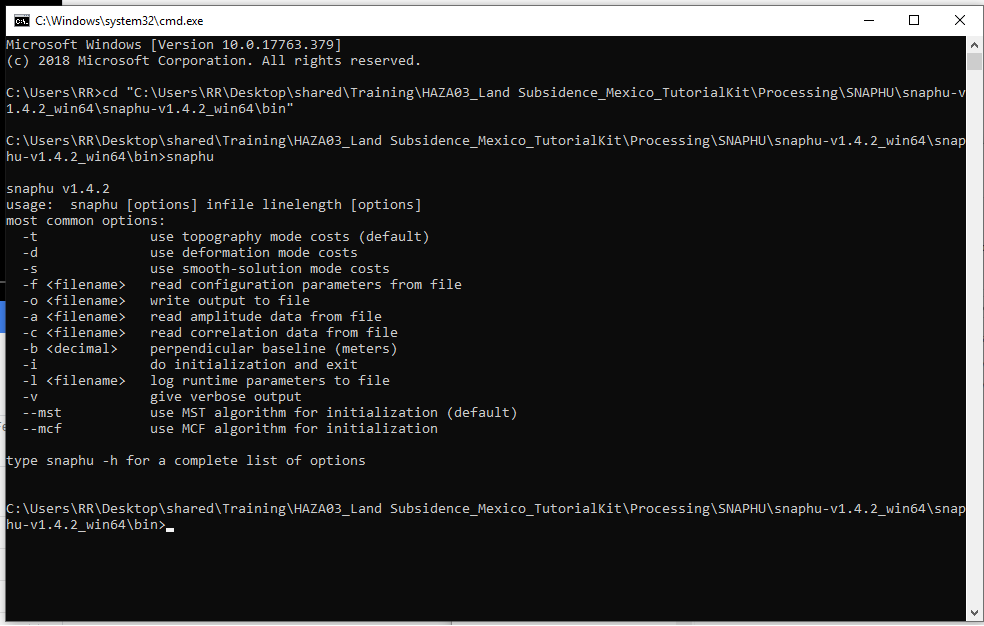
Do I have the wrong directory?
Now, It seems that there is no path of SNAPHU, but you already added it up, according to the previous screenshot, Check up your path again please?
Would you please to try up other way, I think you’re in your right directory,
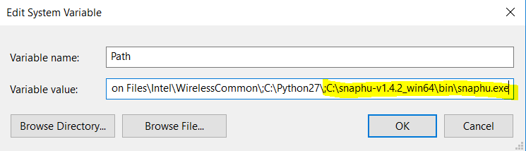
One thing, I think you didn’t add the path in windows as I explained to you,
Please go to your start and type run then type sysdm.cpl in run panel, later on you will have this one
Hit the advance tab, and then Environment variables, go to path and hit edit tab
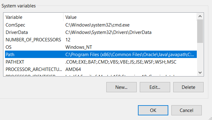
and hit edit text,
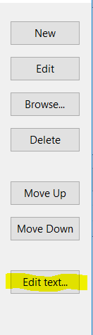
and add the path as I showed to you in previous post, Adding the path in terminal doesn’t solve the issue, as you did, this will only run the snaphu, Hope it helps, enjoy your processing
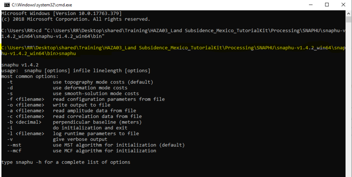
Hi, again!
I think I have the wrong path awhile ago. I just want to confirm if I did it correctly this time.
Thank you so much for replying immediately to my queries.
Hello! I just want to ask if it’s okay working with subsets to generate an interferogram? After doing S-1 TOPS-Split for the two products, I did subsetting to focus on a certain area and save the subset products. Then I am doing now the usual step-by-step procedure. I noticed this below my graph builder. I noticed this below the graph builder. Is it normal?
[quote=“ryeramirez, post:85, topic:4828”]
Hello! I just want to ask if it’s okay working with subsets to generate an interferogram? After doing S-1 TOPS-Split for the two products, I did subsetting to focus on a certain area and save the subset products. Then I am doing now the usual step-by-step procedure. I noticed this below my graph builder. Is it normal?
The first thing you did, was topsarsplit and apply orbit, is that right? What are the step of your processing? they are not clear to me, and would you please to share the screenshot of your graph,
Hi, falahfakhri!
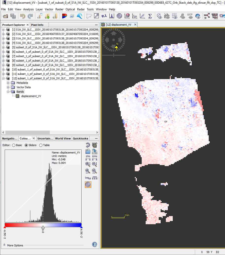
I’ve solved the problem already. I did co-registration with ESD —> debursting —> subsetting —> interferogram formation —> topo phase removal —> filtering —> snaphu export —> unwrapping —> snaphu import —> phase to displacement —> terrain correction. I was able to get a displacement_VV band in the end.
I just want to ask the following:
Sorry for asking these questions. I am really just starting to learn InSAR by myself. And I am very interested with this one. I have attached here the screenshot of the displacement_VV band.
Some of your questions could be found in here,
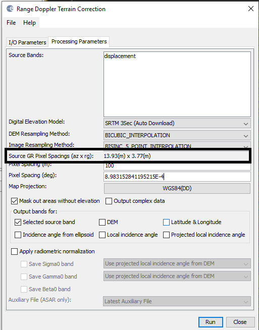
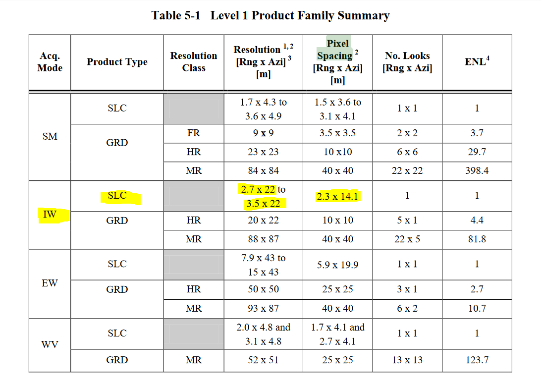
pixel size could be identified in the step of terrain correction,
Concerning your
Since you have only one pair of two dates, the time graph, I think doesn’t work here, but you could extract your displacement results, and to do so, Please take a look at this post
Thank you so much for your immediate response! I really appreciate it. Gladly, I am taking GIS class this semester. The training module you’ve provided is really a big help. I will go through it, do InSAR using the same dataset. This will be my second InSAR training already.
Is this the pixel size?
After doing DInSAR, I plan to do PSI/SBAS as well. I think I can use SNAP also since there is STaMPS export incorporated? Am I correct? Things are getting complicated for me but I am very thankful to all the forums here especially to you.
So it is 13.93m x 3.77m (az x rng). Thank you for providing the table. I will install STaMPS soon. May I know your thoughts also about using other software? For example, DORIS and GAMMA. I’ve read that SARPROZ and SARScape are more commonly used for PSI. Unfortunately, I think these are not open source packages.
I used GAMMA in my PhD, it so flexible software, But it is very expensive, But now I think SNAP, Stamps, This great STEP FORUM, are a great substantial and alternative of any other.
Thank you for sharing your opinion. I think I’m gonna work for now using SNAP StaMPS. Been following some forums here actually to aid my training. I want to ask you about this scheme. Is this reasonable?
I am also wondering how can I produce a final displacement map considering a reference (stable) point (in my subset) that doesn’t change with respect to time.
Thank you. 
Answering your first question, in general the selection of the temporal baseline, it depends on the stability of objects in your study area, the goal of your study, what kind of result you intent to achieve; The far period of S1, is 12 days and 6 days, so the selection short period promotes the quality of the coherence, and hence affects positively in most cases the quality of the produced interferograms.
I’d suggest using the same schedule but in shortest time interval.
Technically concerning your approach please take a look at this post,
and please take a look at this,
https://eo-college.org/resources/insar_deformation/
Selecting the reference point let’s call the technique you’d to preform is “stacking” it is still not supported nor the technique neither the selection of the reference point in the step of unwrapping in case of processing a single interferogram,
Here, I’d say that the PSI, SBAS technique using StamPS, is supported by command of selection the reference point, good background information of your study area helps to choose the right stable reference point, also the best master image, technically, please take a look at this post, and also you should be sure about the radius,
In here, if you mean the reference point doesn’t change corresponding to time your data selection, that’s great.
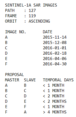
My plan is to observe the behavior of a pavement that experiences downward and upward movements during loading and unloading periods (if this is possible). This is the reason of setting the previous slave image as the new master image for the new interferogram. I have observed that in most papers, for multi-temporal InSAR, only one master image is selected and the rest are slave images (based on temporal baseline). And since I am only getting started with InSAR, I wonder if my ‘proposal’ will meet the results that I want to obtain.
From what I can see from the screenshot, the master images were different from each interferogram (please correct me if I’m wrong). If I am correct, I am now puzzled with Step 5 because it says (13.10.18 as master). More so with Step 6. I want to be enlightened.