They do different things:
Terrain Flattening is a correction of radiometric distortions distcaused by topography. It reduces the effect of topography on backscatter intensity.
RD Terrain correction is a correction of geometric distortions caused by topography, such as foreshortening and shadow. It corrects the location of each pixel based on a digital elevation model.
2 Likes
Hello Sir,
I would like to thank you for all your replies till date, they helped me a lot. Just wanted to ask, why have you suggested to calibrate to beta 0(and not sigma 0) in the algorithms that has terrain flattening.
If i have to perform slice assembly, where should it be applied in your suggested workflow(for GRD).
The reason is this:
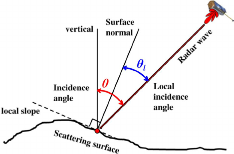
Beta0, also called radar brightness, is the basic calibration of a SAR product. It makes use of an internal calibration constant stored in the metadata. You use it if you don’t have information on the incidence angle (red angle) of your image. The incidence angle is defined as the angle between the surface vertical of the earth (without terrain) and the incoming signal.
Sigma0, the normalized radar cross-section, is an advanced measure of calibration. It takes into account the calibration constant and the incidence angle (which is mostly also known from the metadata).
But if you want to calibrate to Gamma0 which makes use of the local incidence angle (blue angle) you need to have a Digital Elevation model (DEM). The crucial point is that the Radiometric Terrain Flattening in SNAP is based on an algorithm by David Small (http://ieeexplore.ieee.org/document/5752845) which does not use the (local) incidence angle but the area illuminated by the sensor of each pixel. Correcting for the angles before Terrain Flattening would kind of over-estimate the influence of surface orientation towards the sensor. Terrain Flattening therefore needs the basic calibration of Beta0 where the influence of incidence angle is still present.
* NOTE: Since SNAP 8, conversion to Beta0 prior to Terrain Flattening is no longer required, because it has been integrated into the TF operator.
22 Likes
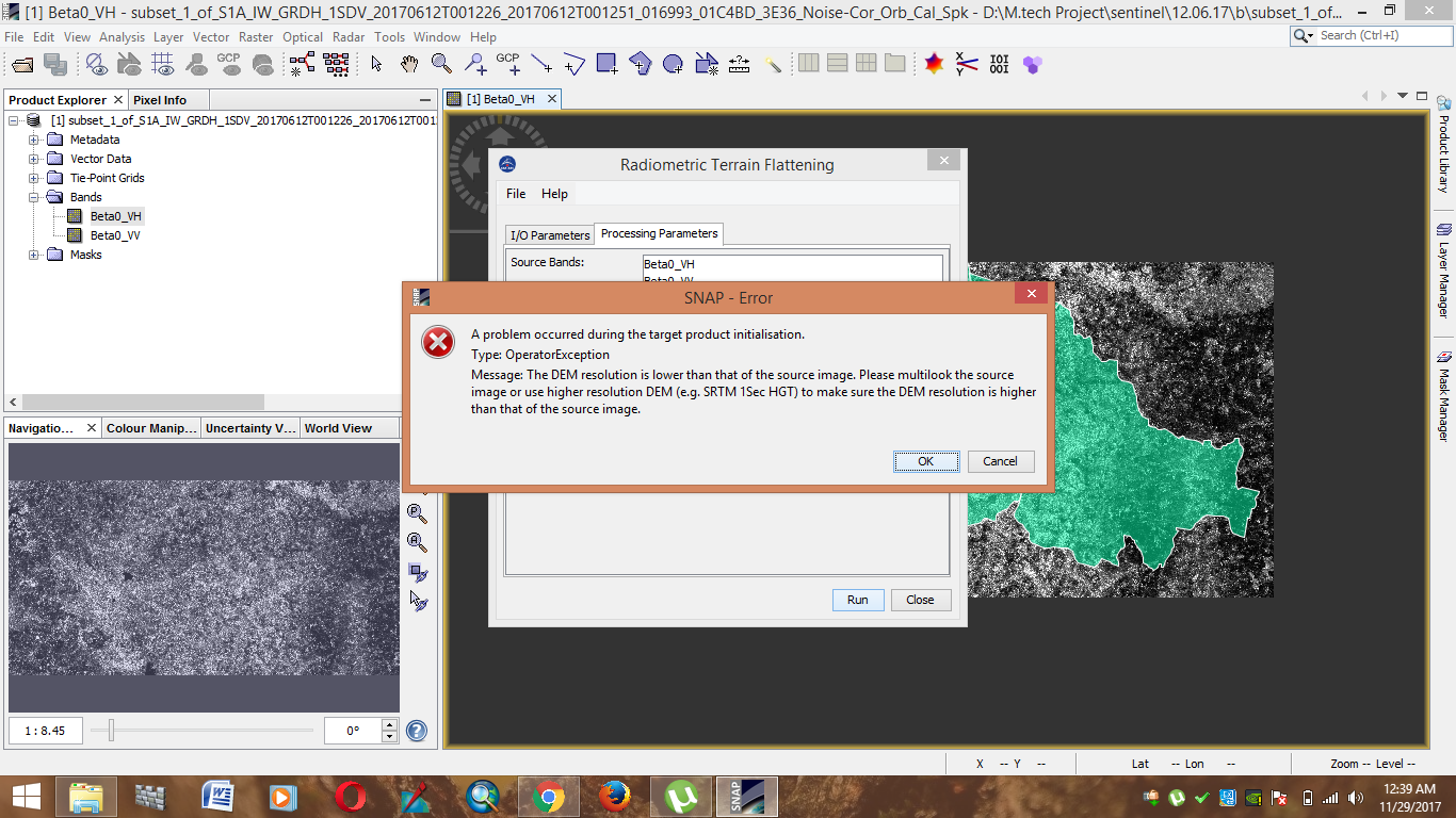
the reason for this error is written in the message. But you can uncheck the re-grid checkbox.
The SNAP software is exploited using the Java language?
Thank you! The resource codes are open access?
Yes, you can use it as you like.
For sentinel-1, the datatype is short complex or float complex?
If you are referring to the i_* and q_* bands of a S1 SLC product, I can say that bands are of data type short.
You can see this by selecting the band and then select Analysis / Information from the menu.
Can you pleas tell me about radiometric correction workflow for SLC data? i ve followed your above suggested steps… But after deburst and orbit file correction i could not calibrate to Beta0? exception says calibration should be applied before deburst?
this could be new since SNAP version 6. In that case it is no harm to put the calibration to B= at the very beginning.
Yes , I have tried the same. So first Calibration to beta0 then deburst and orbit file a=… but i could not perform thermal noise removal it says beta0_VV does not contain thermal noise… So now Applying Speckle filtering… it is consuming lot of time to do speckle filter…
Speckle filtering is optional. You can also generate subsets with TOPS Split first.
Thank you ABraun, i will give a try.
Is it fine, if i firstly subset the GRD data(to my AOI) and then apply the above mentioned steps or should i first perform all these steps and then subset it at last.
Thanks
Both should be fine. If you need to have an exact subset based on coordinates, you can apply the orbit file first.
1 Like
Did you know any scientific papers for those steps at GRD or SLC products?