did you apply topographic phase removal after interferogram generation?
Hi ABraun,
Sorry for late reply.
Yes, I have applied topographic phase removal after interferogram generation.
The processing step of my result is as follow:
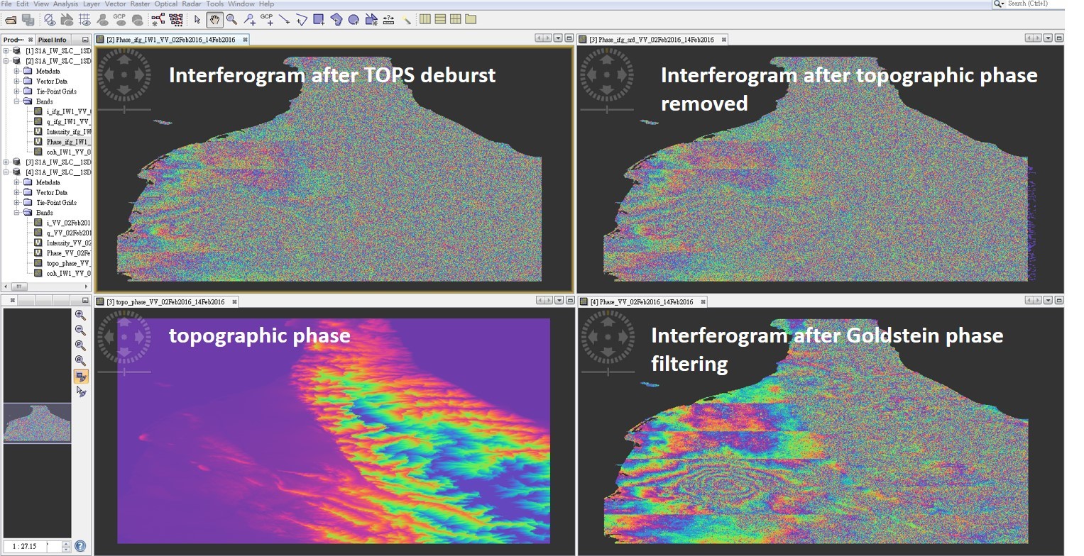
S1 TOPS Coregistration ==> Interferogram Formation ==> S-1 TOPS Deburst ==> Topographic Phase Removal ==> Goldstein Phase Filtering ==> SNAPHU Export
Thank you!!
1 Like
That is all fine. You could apply Range Doppler Terrain Correction in the end and select “Mask out areas with no elevation“. This removes the values over water.
But first you run “phase to displacement“
Should I apply Range Doppler Terrain Correction before SNAPHU export?
And I couldn’t find the selection of “Mask out areas with no elevation“ in Range Doppler Terrain Correction.
I have also tried running “phase to displacement“ after SNAPHU import.
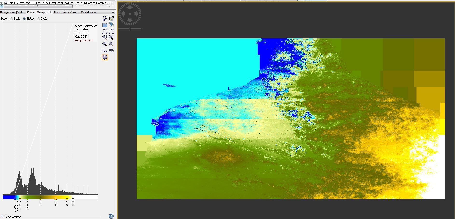
The result of displacement is as follow figure, I think it shouldn’t appear such deformation in the right-hand side mountain area.
Thank you for your help!!
I just saw that it is set by default. So you apply Range Doppler Terrain Correction as the very last step (after import and phase to displacement).
About the patterns:
These are caused in the unwrapping. Did you select DEFO at the export? Ser if MCF and MST make any difference and also try another tile size.
Yes, I select DEFO at export and the initial method is MCF.
I’ll try to change the initial method to MST and another tile size.
And then tell you the result. Thank you very much!
Hi ABraun,
Sorry for bothering you again.
I have tried to use different Initial method and Tile cost threshold in SNAPHU export, the unwrapping results still seem have the same problem.
The result I obtained is as follow:

Cloud you give me some suggestions? Thank you!!
hm, seems that nothing changed. I saw that these patchy areas are not covered in the interferogram at first. So theoretically you can just go on and have them removed in the Range Doppler Terrain Correction as a last step.
Hi,
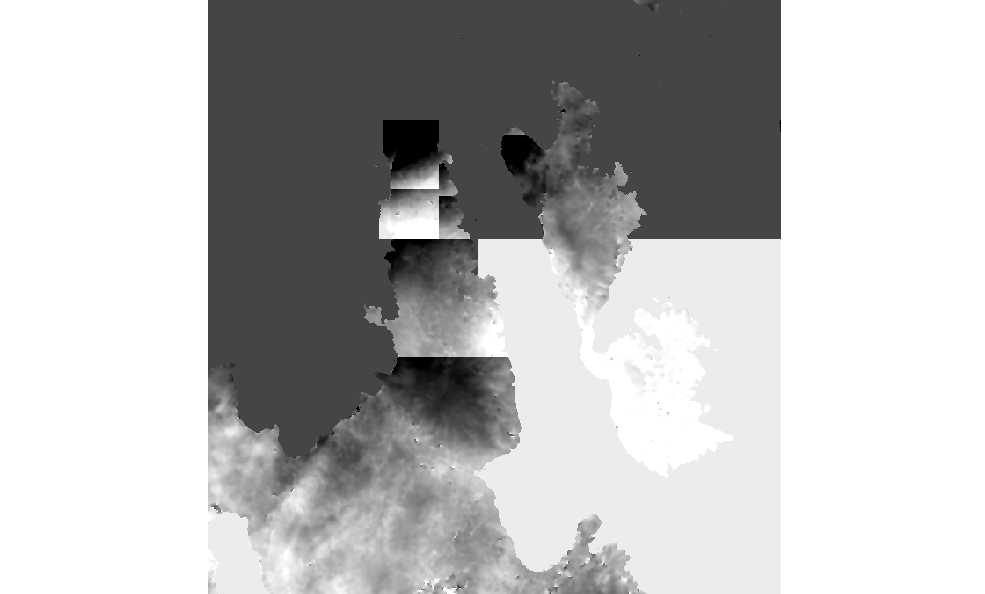
The left one is the DInSAR result and the right one is the result after apply phase to displacement and Range Doppler Terrain Correction as the last step.
I don’t understand why interferometric rings mainly appear in the red block area but we got a large displacement in the yellow block area in the right-hand side figure.
Is there anything I misunderstanding? Thank you for your help!!

two things to try.
- Did your interferogram look alright after Topographic Phase Removal? It could be that a DEM of bad quality introduced the errors and they are already present before the unwrapping step. In this case, choose a different DEM for the topographic phase removal.
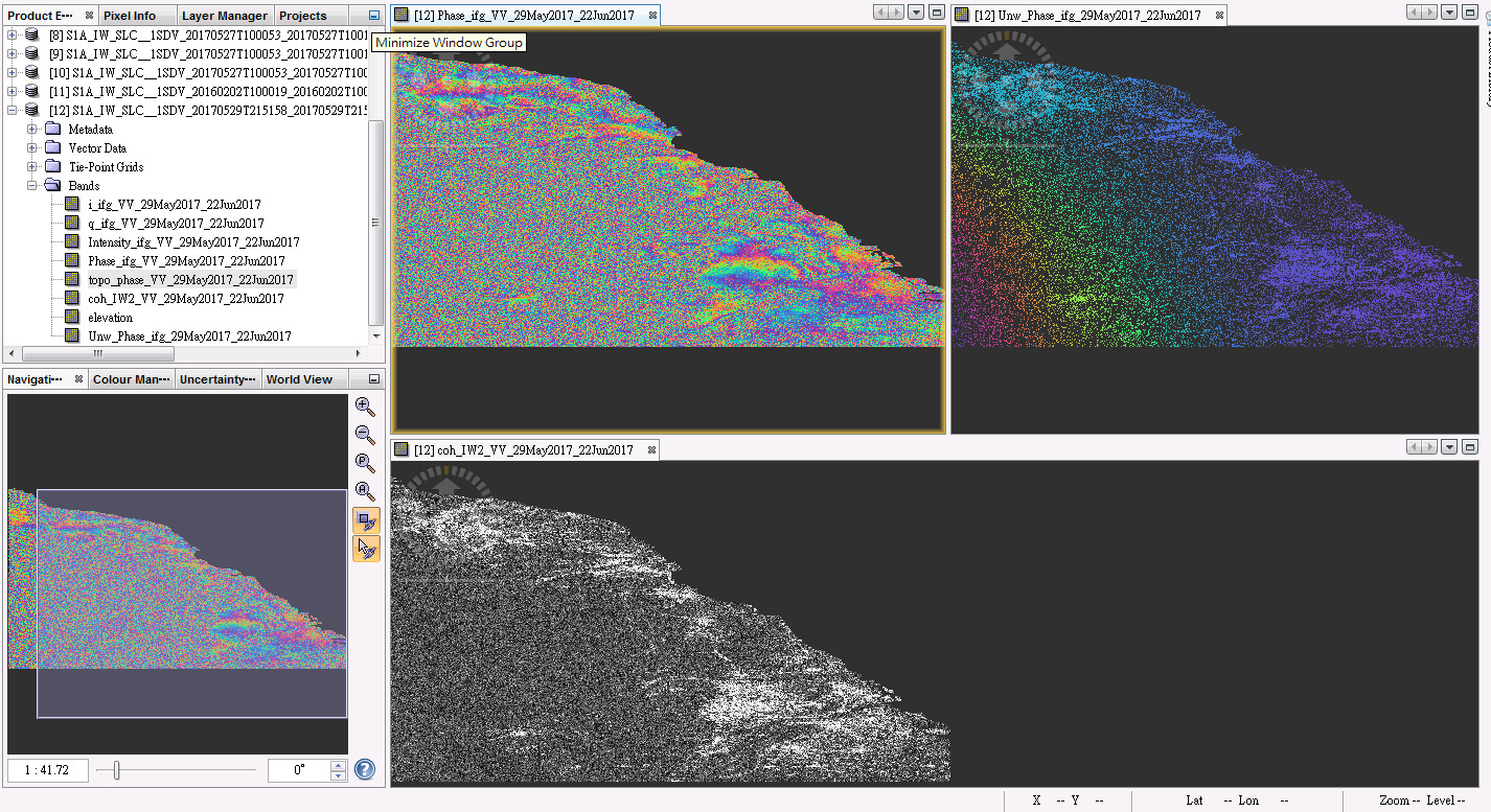
- As it can be seen in one of your screenshots above, coherence is low in some areas. In this regions the DInSAR result is not valdid, especially at the edges of your image where unwrapping errors potentially add up. So try to apply a mask on your image: Right click on your Phase band > Properties and add ‘
coh_IW1_VV... > 0.3’ in the field for valid pixel expression. This removes all areas with low coherence from your interferogram. Of course you need the full name of the coherence band. If the result looks better, you can add the coherence band in the band maths operator to your displacement band as well and use it there for masking.
But first you will have to get a proper interferogram. I agree that with this lines it cannot be used. How many bursts did you use by the way? could these lines be potential borders between the bursts which are merged at the TOPS Deburst step?
1 Like
I used 8 burst, and I think the lines is the borders between the bursts.
Should I merge the bursts before make interferogram?

I chose STRM 3Sec for Topographic Phase Removal. Except for the lines, I think the interferogram after topographic phase removed and filtering is fine. But I’m not sure I’m right or not.
I don’t really understand about masking part. Should I try removing the areas with low coherence from my interferogram before unwrapping step?
Thank you for helping me.
1 Like
actually debursting after making the interferogram is the right step. But that also means that topographic phase removal is not the error but rather debursting the interferogram causes these stripes.
Have you tried a different image pair? Can’t think of a reason why there are stripes after debursting.
You can’t really mask out areas with low coherence but you can define them as invalid so you can concentrate on the areas which provide valid interferometric information.
I explained it here why this can be helpful:
Thank you for the explanation of my question about masking.
And I think the first thing I need to deal with is the stripes after deburst. I haven’t process another image pair, but I will try.
Thank you!
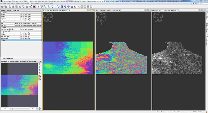
Good morning,
I am using snaphu in order to unwrap some interferograms and see the deformation due to a seism. It is working but as you can see some fringes are not unwrapped, I tried to modify the different parameters (DEFO or SMOOTH, MST or MCF) but no differencies. Someone has an idea how to unwrapped these interferograms ?
1 Like
You can change the tile size in the conf file and run snaphu again. The sharp changes are most likely caused by the tiling of the product.
https://web.stanford.edu/group/radar/softwareandlinks/sw/snaphu/snaphu_man1.html
Thank you for your answer @ABraun , I tested several values but the results are not improved. Is there a logic of values to implement ?
that is the same problem Sharon described above. Do you have the chance to try a different image pair.
Hi Glenn,
Have you solved the phase unwrapping problem? I got similar strange unwrapping result.
I want to get the surface deformation.
And I have tried the following thing, but nothing changed:
- Changed the DEM used for topographic phase removed with SRTM(3sec) and ASTER (1sec)
- Changed the initial method - MCF and MST
- Changed the tiles row and column from10 to 30 and the tile cost threshold to 1000
- Chose different time and area image pair to test
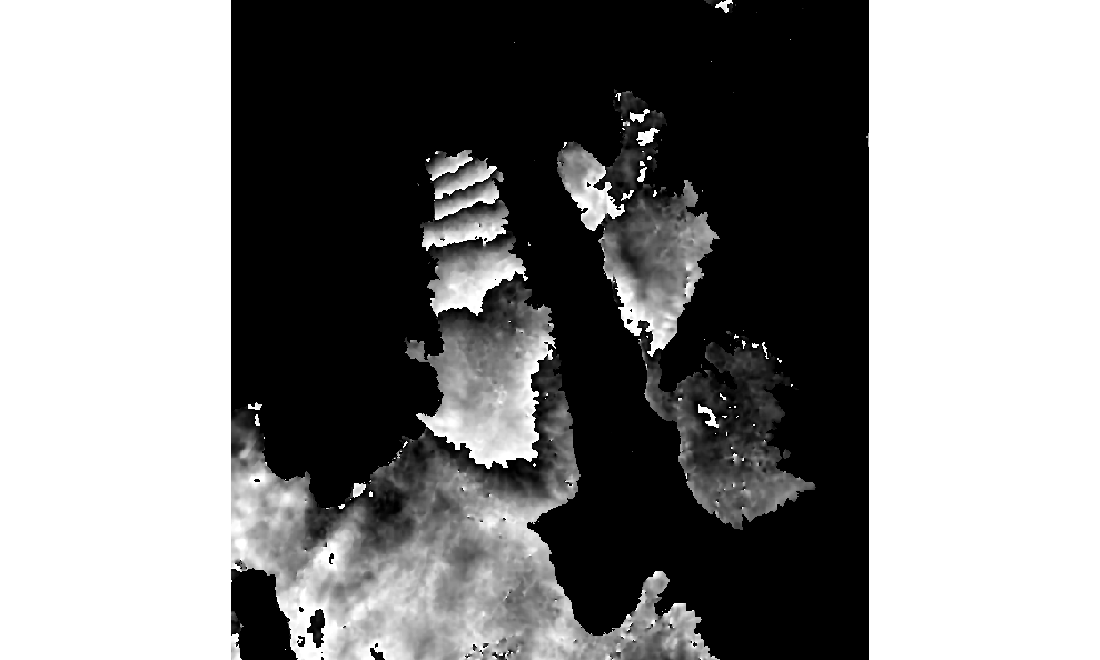
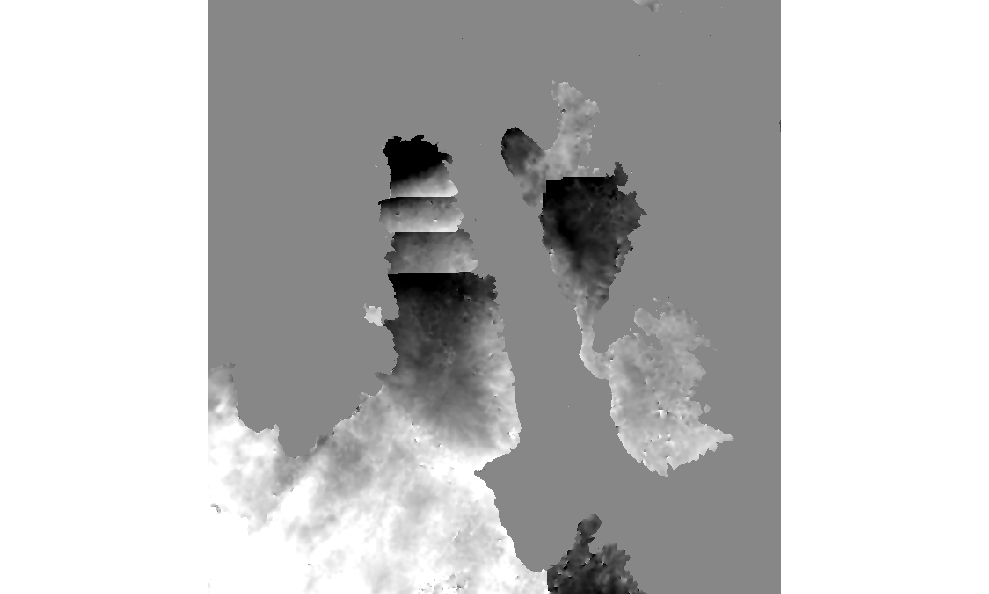
Here are two of my unwrapping results, could you give me some advice or help me to deal with this problem? Thank you!

Best,
Sharon
Hi ABraun,
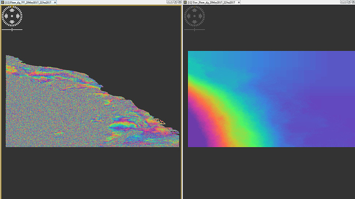
I have tried other image pair for analysis (different time and area). I didn’t get the discontinuous lines after deburst step. But the unwrapping result still looks strange.
This is another case, I want to detect the creep motion of landslide in mountain area.
The left one is the DInSAR result after filtering, and the right one is the unwrapping result.
I have tried the following thing, but nothing changed of the unwrapping result:
- Changed the DEM used for topographic phase removed with SRTM(3sec) and ASTER (1sec)
- Changed the initial method - MCF and MST
- Changed the tiles row and column from10 to 30 and the tile cost threshold to 1000
- Chose different time and area image pair to test
And I also tried to masking by coherence > 0.4. But it seems no help?!
Please help me. Many thanks!
Sharon
maybe the topographic phase wasn’t removed correctly. I don’t know if DInSAR is suitbale for landslides. Because instead of changes in the altitude, many areas just shift laterally. Is Offset tracking an option?
http://sentinel1.s3.amazonaws.com/docs/S1TBX%20Offset%20Tracking%20Tutorial.pdf