Subsidence map in 3d view

Going back to the post of Sept. 8-th.

How to find the “incident_angle” in order to process the data?
Is it in the metadata?

hello ABraun
is there any option in sentinel 1 toolbox from where i can get the wavelength information of my terrasar image…

you said that the crop possess of eliminating the pixel that have low coherence will be done on unwrapped phase … but when i do this process on unwrapped phase … a error message is shown…

but when i did it on coherence image only the required pixel remain no error message shown… is it correct…

I can’t help you when I don’t know the error message.
As you work with the information of the unwrapped phase you need to mask out the locations with low coherence there, of course. It’s kind of map algebra with two rasters: If coherence is low, set unwrapped phase to nan/invalid.

Wavelength is 3.1 cm - I didn’t find it on the rush in the metadata, sorry.

and where i can get the information of incident angle in sentinel 1

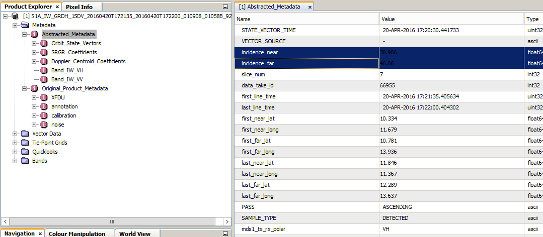
incidence angle is dependent from the distance to the sensor.
So there is always a difference between the far and the near range.:
You find it under Abstracted_Metadata:

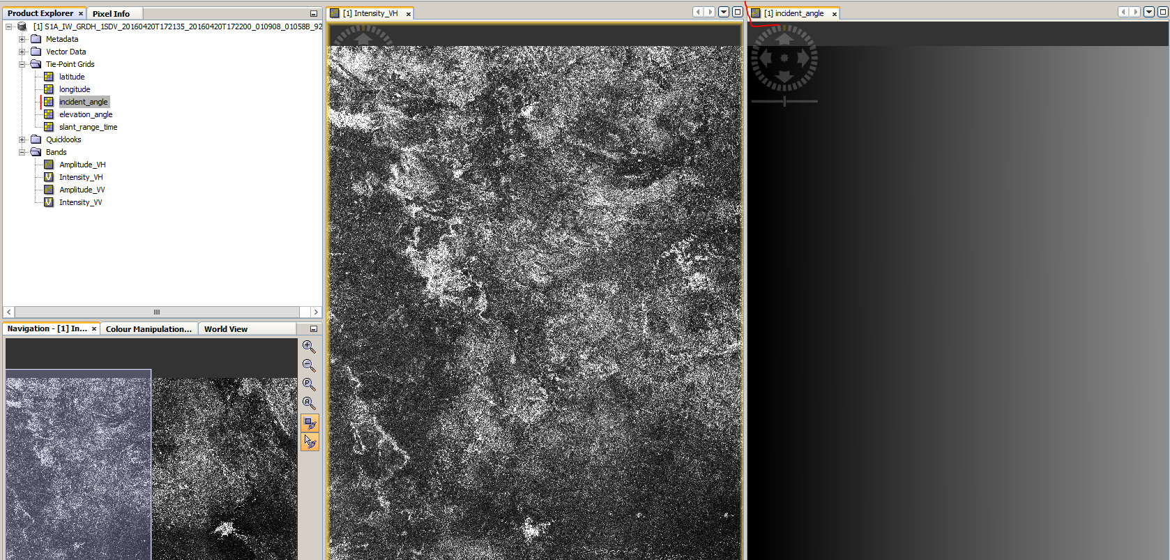
If you want the incident angle of a specific pixel, you can open it as a Tie-Point-Grid:

can u please check weather … the steps I did is right??

  1. this is my unwrapped phase

  1. then I did the band math …

  1. here is new image after doing the band math calculation

  1. then I am opened up the coherence image … and did the crop out process of eliminating pixel that have low coherence value…

then I am identifying the stable pixel, the highlighted one…

what will I do now…

I don’t know how I can it explain it any better than above.
You don’t get information about subsidence from the coherence layer. You only use it as a spatial indicator of quality of your phase information. Therefore, you don’t apply the masking of low coherence on the coherence but on the unwrapped phase information (band 3 in your case). Then you will have the areas where your information is reliable. You can also lower the threshold to 0.4 in order to get larger valid areas.

Sorry, but it seems that you follow a recipe while you aren’t aware of the meaning of the single steps. InSAR is not trivial, undoubtedly. But one should be clear about what is done and why before processing.

and again:

However, there’s a strong ramp in your image wich distorts the result massively. I don’t think you did anything wrong so far but maybe there’s too much time between your images.

2 Likes

Hi Dipankar,

I’d like to say what is mentioned by ABraun in most digestible words, In InSAR Processing chain there are a lot of steps, SNAP concise most of this steps in general and short by including the other within the major steps, the other thing I’d say is each process step has many parameters, in any processing case we try to play with this parameters increase or decrease according for example to study area the per.Basline and TemBasline, Atmoshperic effects and so on, So try to play with those parameters by taking in your account a short TemBaseline for instance in Sentinel-1B only six days, that would clarify many matters for you.

hi ABraun
ok its clear to me…
but when doing the crop process in new band band 2 it will show me the error message …

this is because the coherence is no longer in your stack after Terrain Correction.
Choose it as an input in the RD TC module as well.

Choose it as an input in the RD TC module as well… what does this means

and what will be my next step…

Abraun … i know the theory behind it… but i am completely blank with sentinel 1 toolbox… so …

If you want to mask the coherence you need this layer in your product. Otherwise the ‘valid pixel expression’ has nothing to refer to.

Therefore you need to select all of these source product in the Range Doppler Terrain Correction module so they remain in the output product.

ABraun till now i am ok with the steps… i did the band calculation, eliminating the pixels that have low coherence , and select a point where i assuming no change and its value shows in pixel information tab is 20.48 …

what will i do now

one more thing is that… when i move my cursor both for unwrapped phase and coherence image the pixel information value is gradually increasing in positive figure upward and in negative figure downward respectively,

the result is your subsidence in cm. According to your histogram its mostly positive. But given that you proceeded correctly this is how you technically derive it.

As already stated

You could try eliminating the ramp with a modeled surface but at this point you’re theoretically through all steps.

No ABraun what about last step …

you said

"Select a point where you assume no change and read the value. Let’s say its 45 cm

Subtract 45 from your imagein order to have zero values at those areas with no change. The remaining variation should be due to subsidence between two overpasses"

can u explain … i could’t understood …

if your raster is 20.48 where it should be actually 0 just subtract 20.48 from your raster with the band maths operator to kind of level it to the ground. The remaining variation is the subsidence.

one morething … i am eliminating the pixel that have coherence value below 0.5 …now how am i choose these specific pixel in my subsidence image(band math image) …

some value in subsidence image (band math image) showing positive value and some are negative ones… is positive subsidence i.e the positive value means subsidence or the negative value