yes. the authors do want to have a more polished coherence image because they will do a coherence difference analysis to identify subsided areas due to earthquake.
however, because i am still new in SAR, i am not yet aware of which methods are more appropriate than the other, that’s why i’m following the workflow in the literature.
your thoughts and additional insights would be helpful. thank you.
I made some tests because it puzzled me more that it should.
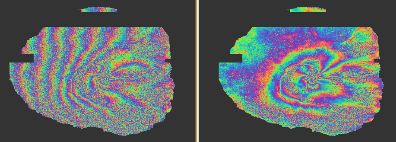
From my perspective, it makes little sense to multilook before making an interferogram. Indeed, the phase information of each image is changing rapidly from pixels to pixels. Multilooking the data at that moment is ok when you look at the intensity, but you completely destroy the phase information. Nonetheless, SNAP lets you do it. You can create an interferogram based on multilooked SLC images. This problem does not arise when you multilook a “slowly varying” phase information such as present in an interferogram.
Not surprisingly so, the interferometric phase of let’s call “a priori” and “a posteriori” is totally different. According to me, the “a priori” multilooking is not correct in any way. Please correct me if I am wrong.
left : a priori multi looking
right : a posteriori
Concerning the article, my question was rather : did the authors computed the coherence during the interferometric process or after multilooking ?
edit: Ok I realized you cannot compute the coherence after multilooking since you miss the information of the master and slave image needed in the equation. For this simple reason, SNAP does not allow you to compute coherence after multilooking the interferogram
For these reason, If anyone try to replicate what the authors did, I would do as stated before. Not saying that this is exactly what they did.
Thank you for comparison @qglaude
I totally agree that altering the slant range data is drastically changing the phase information in a way it shouldn’t. I did not propose this in here either.
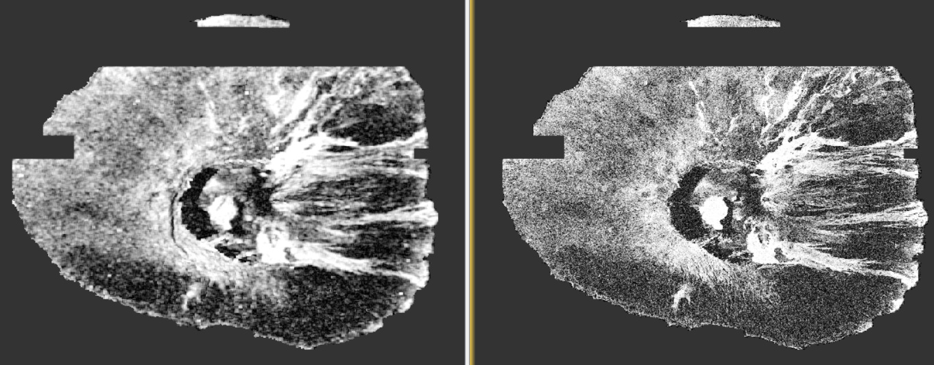
What I thought was that the coherence could look different (better?) when you apply multi-looking before its calculation (at least as proposed by the authors of the study [as I undestood them]). Would you mind comparing the coherence as well and share it in here?
(by the way, looking at coherence histogram, the a priori coherence is not better)
I don’t know… I never investigated that deeply, but I am very not fan of using the coherence of a priori multilooked SLC master/slave. Even if you’re not using the phase, that’s this phase which is involved in the computation of the coherence. And to be honest, I’m not even sure to what the interferometric phase of multilooked product could be linked. I am afraid that there is something wrong there, but I cannot demonstrate it. If someone can help me, this would be great.
To explain it with my hands, the combination of wavefronts forming the the interferometric signal is noisy but still has trends. Spatial aggregation makes sense and this is what the multilooking does. It produces a signal with higher SNR. However, the two signals individually are spatially varying way too much. The phase information is greatly undersampled. In my understanding, the spatial aggregation is simply not allowed (signal theory and so on). This is only their phase difference that produces a slow varying pattern.
thank you for this comparison. I think it iss very interesting how the two approaches result in different coherence patterns. I fully agree that the a priori coherence is not better than the standard way of computing it. It is rather grainy and seems to have less contrasts than the right one.
And you are of course also right that from a theoretical perspective it does not make much sense to multi-look the complex stacks before interferometric processing. I would not recommend it either, but many coherence-based approaches suffer from clear patterns (unless large stacks of coherence are combined). So, no matter how the authors intended (in the meanwhile I also think I misunderstood it), detection of changes from coherence sometimes benefits from higher contrasts and rather homogenous areas instead of gradual changes. This is why they probably just applied a filter on the slant range coherence.
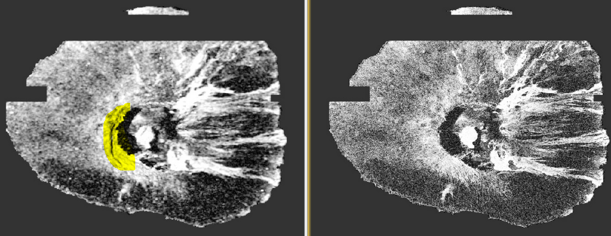
One thing I noticed is that a small difference occurs in the multi-looked coherence. It is probably an artifact due to signal shadow, but it is not present in the right product. Depending on the application (I was thinking of lineament mapping with radar shadows) this could also be something desirable.
By the way, @mengdahl is involved in a research project on coherence-based landcover mapping (https://sincohmap.org), it is also interesting how they deal with the information content of coherence, the impact of polarization and the role of the temporal baseline.
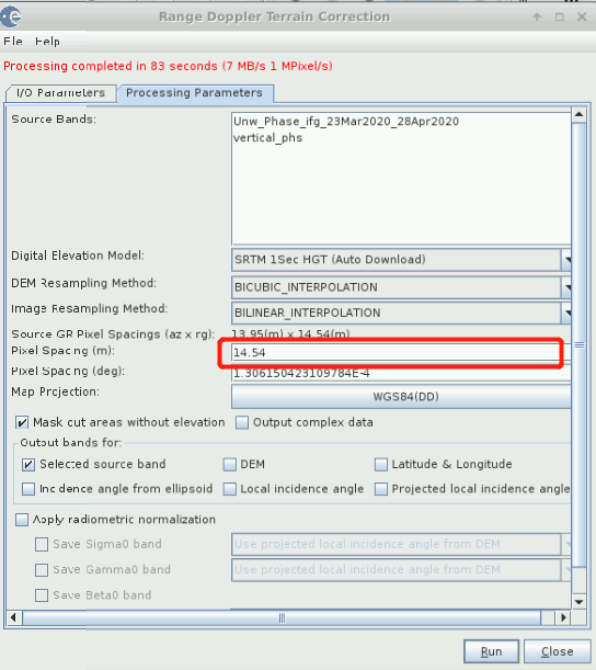
But in the end I’m entirely with you: It does not make sense in most of the cases. So, coming back to the original question it is still not clear to me how the authors end up with a spatial resolution of 150 x 200 m spatial resolution. Maybe it is just me, but I more and more notice intransparent or incomplete method description in MDPI journals, probably because of their review policies which aim at fast publication at the cost of less critical reviewing.
Is it possible they used 6x2 for coherence estimation window & multilooking to end up with one coherence & intensity value per a 30x40m pixel, and then post-processed with 5x5 pixel moving average which would downgrade the resolution to 150x200m?
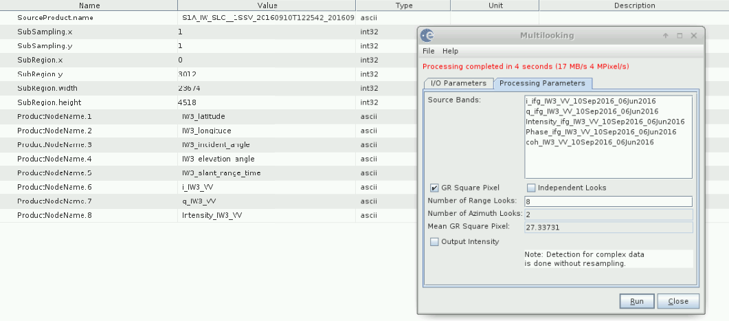
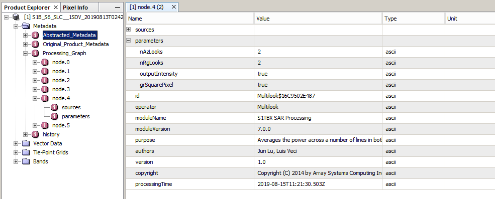
You can check in the metadata under history what parameters you had selected.
The multilooking operator also interactively shows the output resolution (depending on the number of range looks)
Thank you , sir. As is shown in my picture, is the resolution 27.33731 meters? If it is, by the way, how could figure out 27.33731 meters with thoese metadata under history?