Hi, I am attempting to co-register multiple iceye sar images. Certain slave images are coming out blank though. Appears as if the images with incidence angles similar to the master are processing successfully but the rest are coming out blank.
Coregistration only works on data from the same track, especially when data has high spatial resolution. Different viewing directions and incidence angles can introduce shifts which exceed the capabilities of coregistration approaches.
You could pre-process (calibrate, terrain correct) all data and then create a stack (or re-try coregistration with “product geolocation” as initial offset method instead of orbit).
After pre-process (calibrate, terrain correct), can I continue to create interferograms as I did with Sentinel data?
I.e. Radar → Coregistration → Coregistration and then
Radar → Interferometric → Products → Interferogram Formation?
Any parameters I need to look for?
Maybe you can first share your data and aims. Calibration and coregistration are mutually exclusive in some cases.
Some general remarks/questions:
If you want to do interferometry, calibration is not necessary. You imply that it is essential, why?
Radiometric calibration makes images of several dates comparable by converting backscatter intensity to Sigma0. This compensates for differences resulting from sensor specifics and global incidence angles (not looking directions though).
Why did you apply DEM-based coregistration instead of the one based on cross-correlation between the images.
Terrain correction is needed because SAR is a side-looking system and contains foreshortening effects induced by terrain variations. Please have a look at chapter 2 of this book: SAR Handbook
You use a DEM to reduce these effects, but the results are dependent from the quality of the DEM
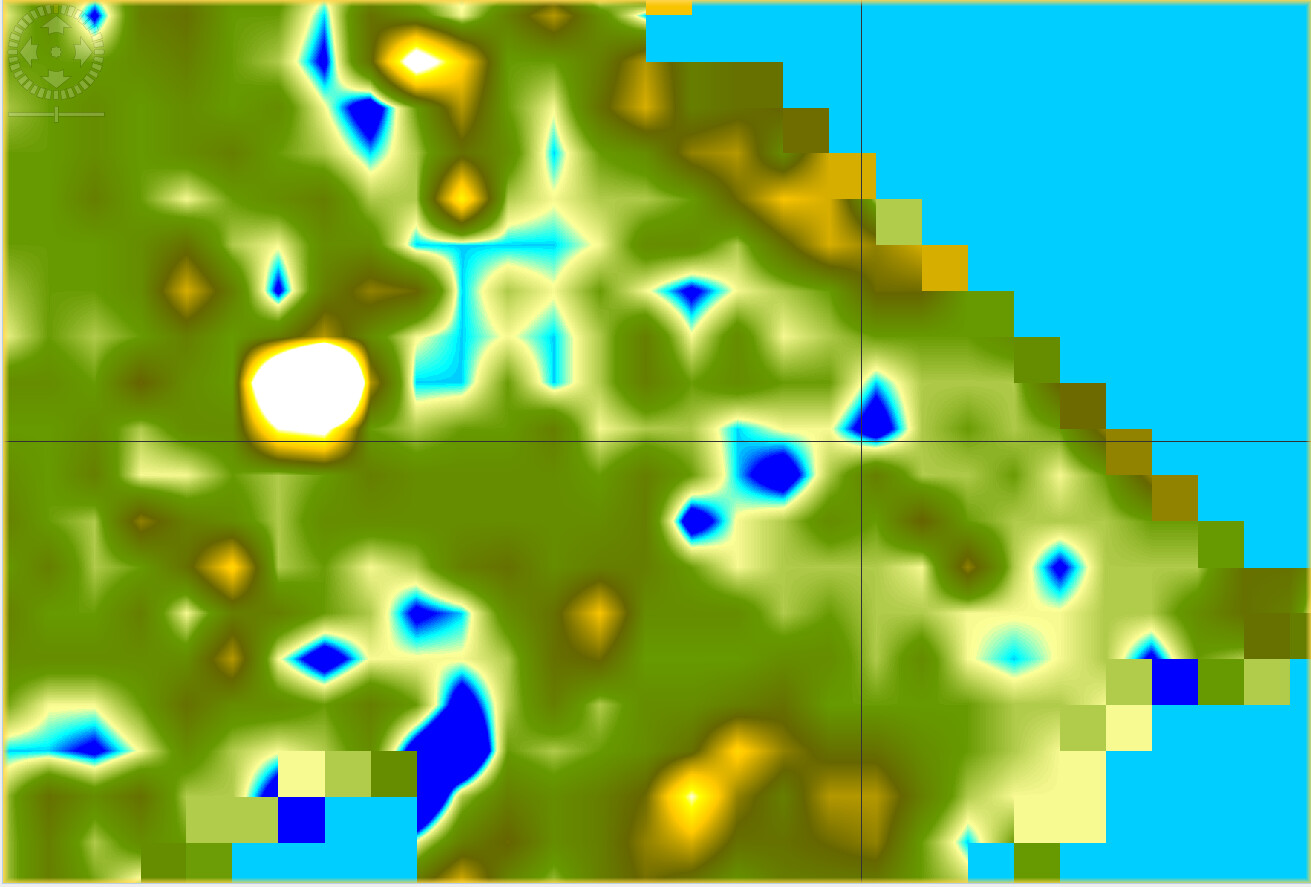
The blurring occurs when pixels are shifted to their actual location. The information in foreshortened areas cannot be restored so the missing pixels are just estimated.
The brightness of your image is defined in the Color Manipulation tab in SNAP. The pixel values are not changed during the Terrain Correction (only with bilinear resampling to a new grid and spacing)
Maybe you can clarify your questions based on these points. I feel that your understanding might base on some false assumptions.
Thank you for the taking the time and writing all these.
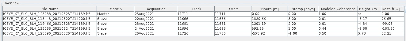
I have 5 spotlight images from the end of August 2021 taken by the Iceye SAR constellation. I obviously can’t share the data since it is very expensive.
My goal is to run ACD on this set of images, that’s why I need to do coregistration.
I wrote that calibration, multilooking and terrain correction are essential since this is what written in the Iceye-Snap tutorial - ICEYE SAR Data in SNAP, under ICEYE SLC DATA PRE-PROCESSING.
I asked about these stages since, as I understand, they are needed for SAR images in general and not for Iceye specific. I used Snap with TerraSAR and Sentinel in the past, for coregistration and ACD, but I was not instructed to carry out calibration, although it was always a set of images of several dates. I never saw any reference for radiometric calibration when dealing with TerraSAR and Sentinel.
The same for terrain correction, it is not part of the sentinel PS pipeline as described a lot in this forum, for example. For TerraSAR, I found a Snap pipeline that I used in the past and it doesn’t do calibration or terrain correction as well.
So my questions are basically - what happened that Iceye guides to do these stages?
Why did I apply DEM-based coregistration instead of the one based on cross-correlation - at the beginning I did the cross-correlation and then saw the blur at the end of the process, after terrain correction, and I tried to eliminate the source for that so I did another type of coregistration.
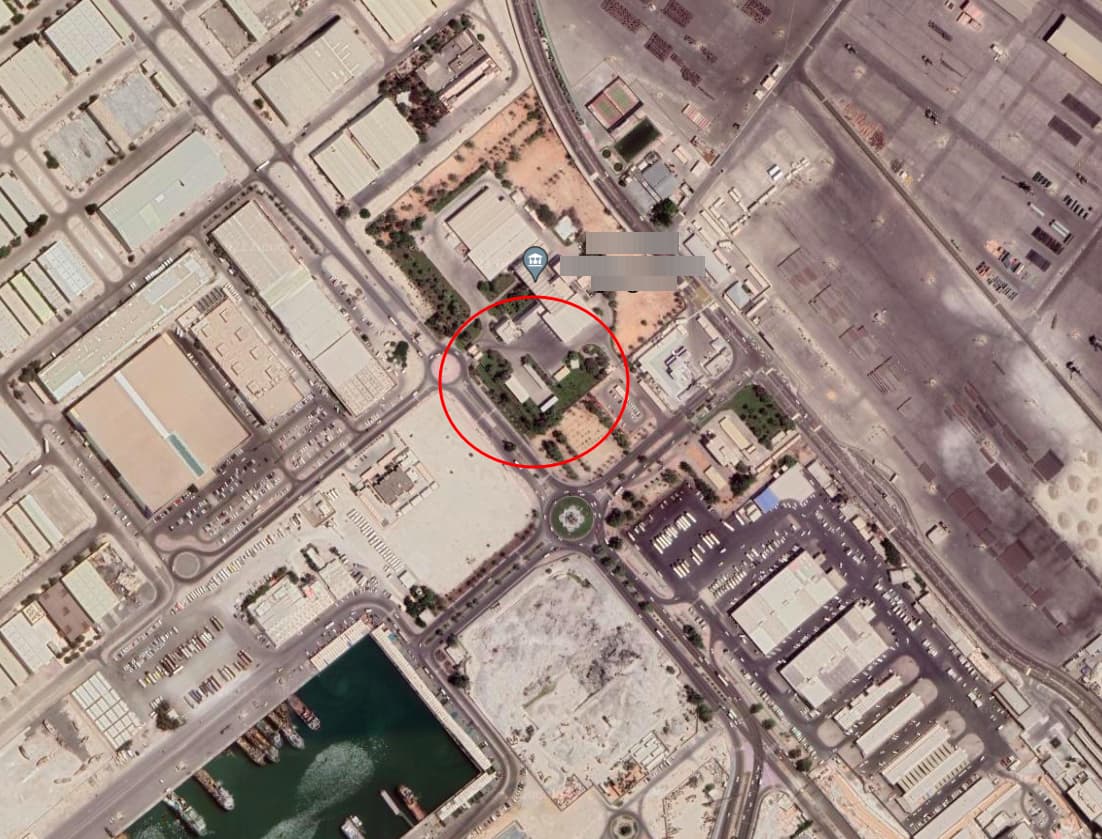
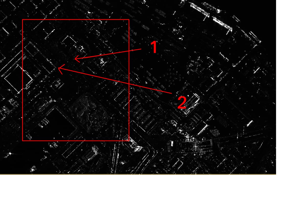
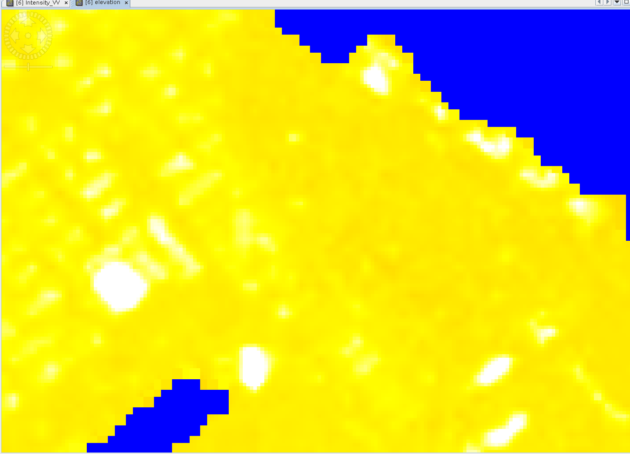
The blurring occurs when pixels are shifted to their actual location - so why does it happen in that location? as you can see in the optical image, the area is flat.
Sorry, this was not clear from your initial post. So in your case calibrating makes sense because you want to compare intensities of different dates. Calibration makes sure that the differences caused by the sensor are kept as small as possible. If you ask me, it should be applied for every multi-temporal approach, regardless of the sensor (unless you want to perform interferometric analyses which primarily use the phase instead of the amplitude information).
Multi-Looking is not mandatory. It helps to get better image quality, but at the cost of reduced resolution. So it depends on how much loss of spatial detail you can accept in your data.
The reason is that the Sentinel-1 PS pipeline looks at the changes in the phase, not primarily in the amplitude. PS cannot be compared to APC, therefore the pre-processing is different. For example, the final geocoding is done in Matlab and therefore not part of the PS preparation in SNAP.
If all your ICEYE images are acquired from the same track (I would consider this a prerequesite of multi-temporal amplitude change detection over urban areas), you can use the “common” coregistration module and use the “orbit” as initial offset method. The DEM-based coregistration is an alternative but I would not recommend it for VHR SAR data unless you have a VHR DEM as well.
The quality of terrain correction applies on the quality of the DEM, as @mengdahl said. You can select “DEM” as an additional output to check if there are variations in the DEM data. Which DEM did you use by the way?
could have many reasons. The DEM is upsampled to the spatial resolution of the SAR data this can also often introduce weird patterns. It also depends on the origin of the DEM and if it contains surface heights or not. So maybe comparing different input DEMs and their impact on the terrain correction result could help to avoid “false” geometric corrections.
DEM-based coregistration follows a different principle. A DEM is used to simulate the variations in backscatter intensity purely based on topographic variations (e.g. hills, which are barely present in your area) and uses these to overlay the DEM and all input radar images. But as the spatial resolutions of the DEM and the ICEYE images is too different, I see no benefit.
In contrast, the Range Doppler Terrain Correciton uses the DEM to shift each pixel at its exact location a the Earth’s surface based on the height information from the DEM. This potentially introduces more errors than observed in the coregistration because in the latter all non-matching areas are ignored.
DEM-assisted co-registration is for pair with large height differences and long baselines. It does not make any sense to use it in flat cases. I notice the help does not explain this or give references. (@jun_lu please note. )
In addition it looks like your chosen DEM is of low quality, probably one of the global altimeter DEMs. Try the lightyears better Copernicus 30m one for terrain correction instead.
Multi-Looking is not mandatory. It helps to get better image quality, but at the cost of reduced resolution.
If you lose resolution, in what way is the quality gets better?
The reason is that the Sentinel-1 PS pipeline looks at the changes in the phase, not primarily in the amplitude. PS cannot be compared to APC, therefore the pre-processing is different. For example, the final geocoding is done in Matlab and therefore not part of the PS preparation in SNAP.
(1. ACD, not APC).
2. Isn’t terrain correction needed when phase is the basic material in use?
3. If I am not wrong, terrain correction is not one of the StaMPS steps -
Step 1: Load data
Step 2: Estimate phase noise
Step 3: PS selection
Step 4: PS weeding
Step 5: Phase correction
Step 6: Phase unwrapping
Step 7: Estimate spatially-correlated look angle error
Step 8: Atmospheric filtering
If all your ICEYE images are acquired from the same track, you can use the “common” coregistration module and use the “orbit” as initial offset method.
Here is the tracks list, what do you think about it?
Speckle effects are reduced, you get more homogenous areas.
only at the end of the processing, for example when you converted your phase to displacement, then you terrain correct the displacement raster as a last step.
It is not called terrain correction, but the location of the persistent scatterers is estimated within the process.
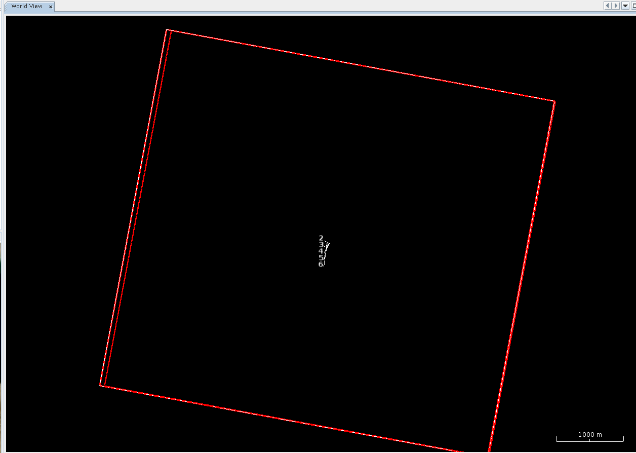
looks like your data is acquired from different tracks (= different look direcitons and different angles). Can you please show their footprints on the World View tab?
Any building will look different in every image, because in one you might see the right wall and in the other you see the left wall. ACD will falsely detect this as change, but it’s just the result of different angles.
This has 90 m of spatial resolution, please try the Copernicus 30m DEM for a comparison.
yes, probably they come from different satellites. If they were from different tracks the footprins would be shifted or rotated. It’s unlikely that they are from different tracks and different incidence angles. Maybe you can check the orbit direction and incidence angle of all products in the metdata.
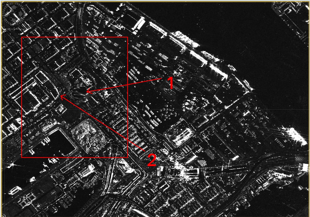
OK, so the Copernicus 30m DEM does not cause a blur in that area, and the distortion is less, but now there is distortion in other places, like the building in the upper right area next to the ship.
So the question is - do I need to terrain correct in my situation? flat area, no need for phase content.
(In the future I might apply CCD, which needs the phase data. Would terrain correction be critical then?)
as an alternative, you can apply Ellipsoid correction. It would not introduce distortions but the locations of the changes would have to be interpreted with care. Depends on if you want to overlay these data with other data (e.g. shapefiles of buildings)