I am afraid this is trivial but I am unable to find the answer: when mapping corner reflectors using SNAP for interferometric analysis I get elongated shapes rather than the point-like reflectors seen on Sentinel Hub EO Browser
My flowchart is as follows (Makefile calling gpt):
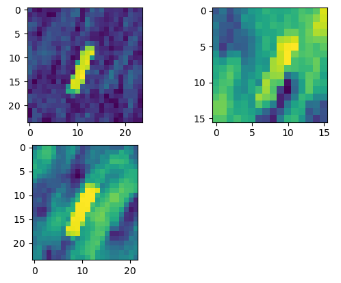
so Split → Apply precise orbit → Back Geocoding → Interferometry → Deburst → Topo phase removal → Multilook → Goldstein phase filtering → Range Doppler Terrain Correction resulting in the attached thee corner reflector areas:
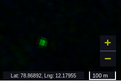
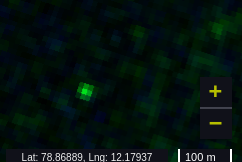
whereas Sentinel Hub EO Browser shows for both dates are “perfectly” overlapping:
I have removed ESD since I am working with a single burst and have made as sure as I could that the registration was correct by displaying the RGB image from stacking.
Any obvious step I am missing?
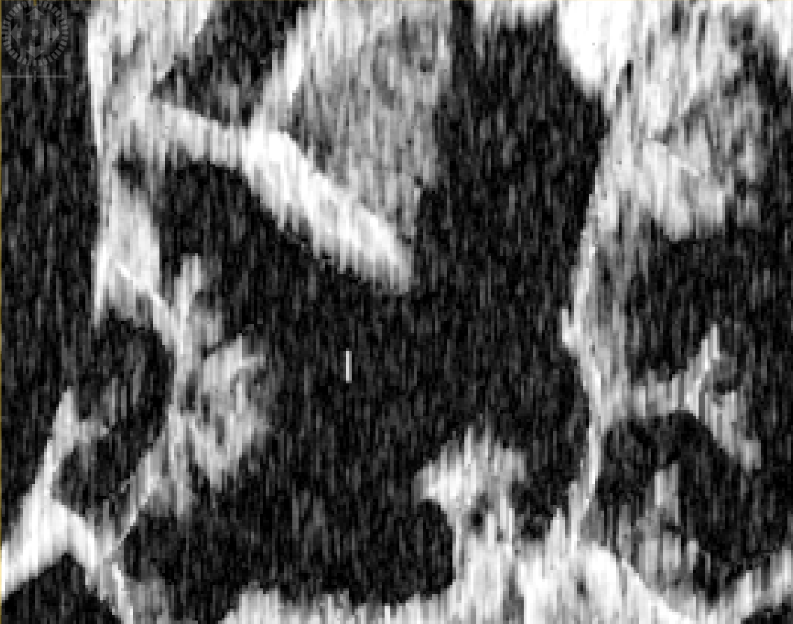
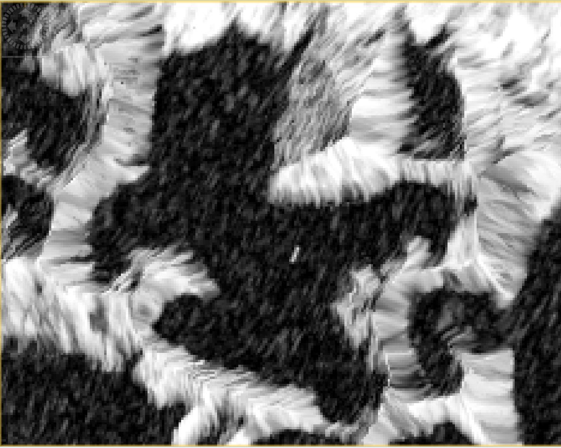
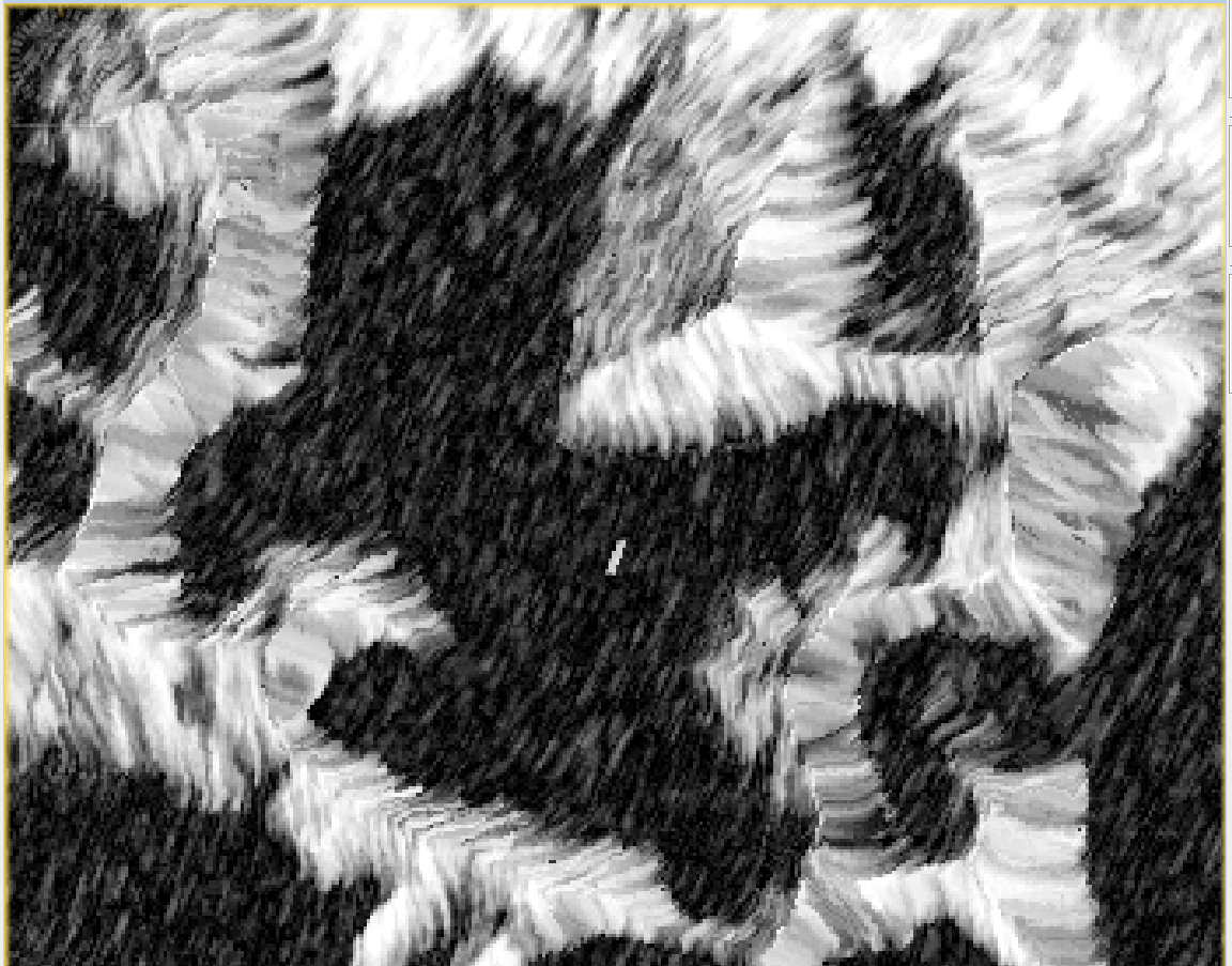
Following your comment about the square DEM, I went back to check with SNAP each individual processing step and up to (and including) TopoPhaseRemoval I get a single high-coherence pixel where the corner reflector is located. The elongated shape appears during Multilook processing, which I found awkward since I was running gpt Multilook -SsourceProduct=... -t output without Az and Range arguments so I would have thought they are 1x1.
I hence went back to basics and checked the role of Multilook that I understand as a smoothing filter which is actually not applied in https://step.esa.int/docs/tutorials/S1TBX%20TOPSAR%20Interferometry%20with%20Sentinel-1%20Tutorial_v2.pdf but in http://step.esa.int/docs/tutorials/command_line_inSAR_processing.pdf
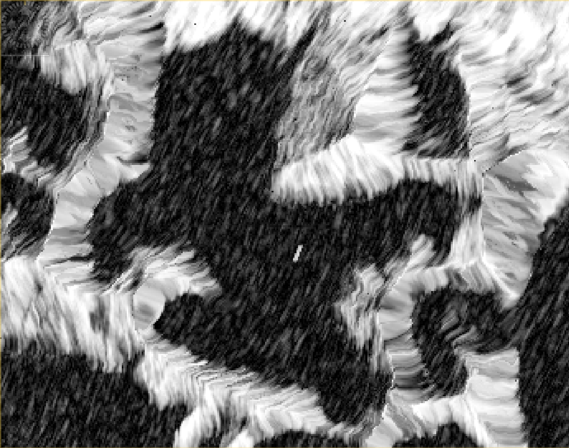
Top after Goldstein filtering but no Multilook, bottom with Goldstein after MultiLook
So my question is: what would be the processing advice when targeting a point-like reflector such as a corner reflector. Are MultiLook (and even Goldstein filtering) advised in this circumstance or is Split → Orb → Back Geocoding → Interferogram → Deburst (as shown in the second page of the latter link) sufficient for corner reflector displacement measurement?
Nevertheless after Terrain-Correction I end up with an elongated reflector, with (top) or without (bottom) MultiLook processing, which sounds a bit obvious considering how the non-ML image looks prior to terrain correction.
Would it actually make sense to perform the phase analysis on the output of the Goldstein filtering prior to TerrainCorrection, since I know where the corner reflector is and do not need the geographical coordinates, and avoid spreading energy with this last processing step?
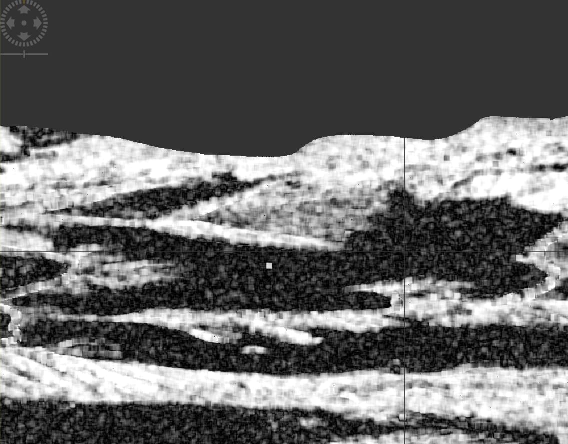
I’m still guessing the terrain-correction step creates the problem. What does the reflector look like in radar-geometry, before the terrain correction step?
Usually people working with corner reflectors want to preserve the resolution, so no multilooking at all or a minimal amount (for example 4x1 in range and azimuth).
I believe the images prior to terrain correction are the first one I displayed in the previous post (no multilook, with the corner reflector right in the middle as the sharp bright spot in the correlation map) and second one (with multilook, with the corner reflector appearing as an elongated vertical line).
Thanks for clarifying the impact of multilook when working with CR.
After reading How to import an external DEM into SNAP? - #19 by Parisa I thought the issue might have been that the DEM I am using is in projected coordinates UTM33N but saving as WGS84 and processing again the whole sequence leads to the same elongated shape after Terrain-Correction. Could it be related to the high latitude (which is the reason why I cannot used SRTM)? although I cannot imagine a relationship between latitude and DEM deformation.
Well, corner-reflectors are not elongated and EO Browser is using SNAP for processing S-1 data, so the problem must be somewhere in your processing. To me it looks like you are erroneously terrain correcting non-square radar geometry pixels into square map projected pixels and the ~5 time higher resolution in slant-range is making those reflectors look elongated.
BTW I’m not sure you should want to use goldstein filter either, the corner-reflector phase is unrelated to the phases of the nearby pixels so I don’t see how any “smoothing” could help.
Thank you for confirming that Goldstein is also not needed, that confirms my new understanding of phase analysis of the point-like target.
I did try running the whole processing with SNAP using the GETASSE30 since working at 79 deg N prevents using SRTM and I obtain the same elongated shape, which now that you state it sounds obvious since the target is square in SAR geometry. I wonder though how Sentinel Hub EO Browser ends up with the fine square shape in geographic coordinates … in the mean time I’ll complete the analysis in SAR geometry where I can find the target and identify the phase in the non-projected framework.
Thank you for your support.
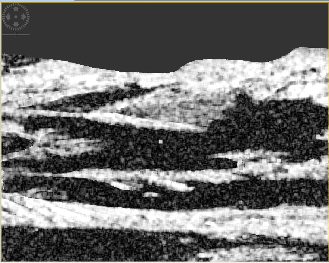
Here is the result of deburst, i.e. no filtering after Interferometry → Deburst (top), and bottom is the Terrain Correction executed in SNAP with my DEM by selecting Nearest Neighbor on both DEM Resampling and Image Resampling instead of the Bilinear Interpolation. Same result though.
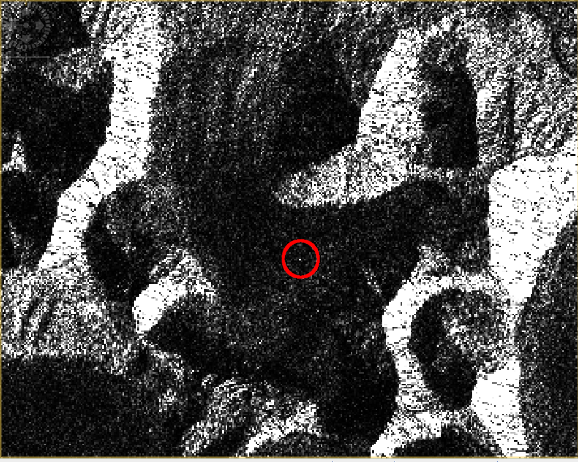
Very interesting indeed: Orbit → Deburst → Terrain Correction using my DEM with projection to WGS84/UTM33N does yield a single pixel! I highlighted the corner reflector manually (red circle) to make identification easier.
Got it … the default configuration of SNAP Interferogram formation is to compute the correlation on a 10 range-pixels and 2 azimuth-pixel window size. whereas the default setting of gpt is 10x10
Parameter Options:
  -PcohWinAz=<int>                        Size of coherence estimation window in Azimuth direction
                                          Default value is '10'.
  -PcohWinRg=<int>                        Size of coherence estimation window in Range direction
                                          Default value is '10'.
setting -PcohWinAz=2 in gpt Interferogram leads to square pixels after TerrainCorrection.
So that seems to be solved.
Just a last question to make sure I understand all the processing steps: am I correct in understanding that the Topographic Phase correction is “just” a DEM-generated constant phase term that I can also remove for corner reflector double-difference displacement investigation?
Thanks
I am reviving this thread after a few years since I am now assessing DInSAR analysis in complement to magnitude analysis.
I have concluded that the Terrain-Correction is needed to reach the projected UTM33N coordinate system and that while each GeoTIFF image might cover slightly different bounding boxes, this difference is documented in the header and allows for finding the pixel positioned at a known geographic coordinate.
The processing script with the sequence is documented at
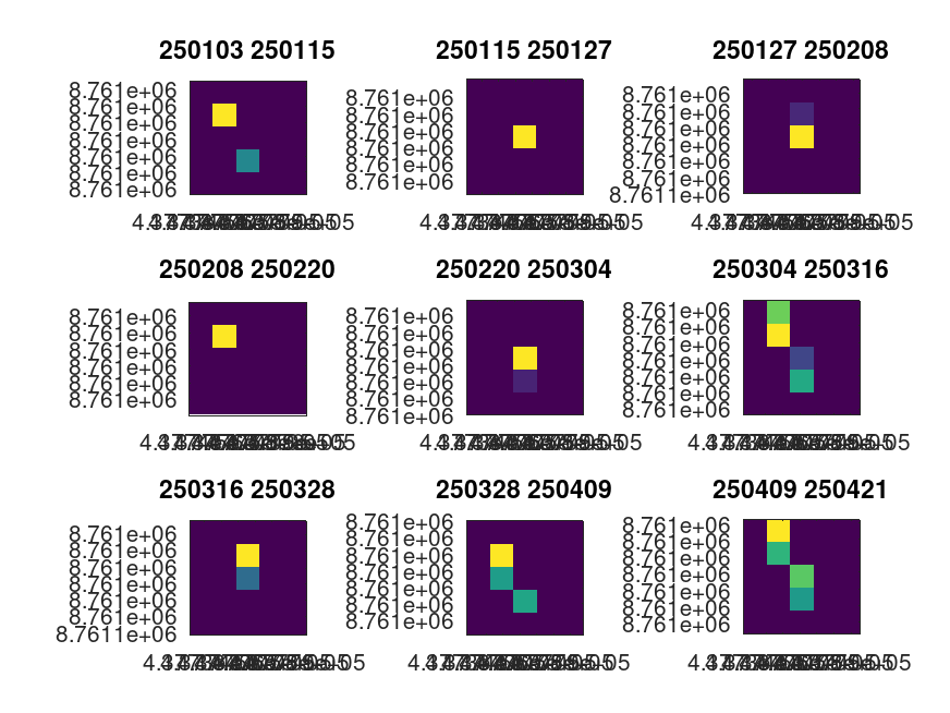
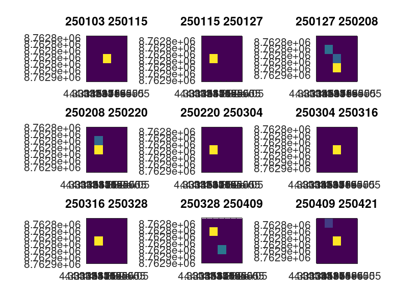
but as seen below, two corner reflectors positioned at known coordinates seem to shift from one pixel to the neighbours:
Each map is the intensity map around the known corner reflector coordinates (two figures for each corner reflector) at different date differences as shown in the title of each subfigure.
I suspect that the unusable phase information is at least related to this discrepancy in the target position, since the registration (Back-Geocoding) is supposed to align with sub-pixel resolution.
Are all corner reflector signal not supposed to be located in the same pixel? Is there any obviously wrong in my processing script (Split → Apply orbit file → Back geocoding → Interferogram → Deburst → Terrain Correction to reach the geographic projected coordinates).
I did read about Perpendicular baseline and decided to compare each successive image to minimize the satellite position difference between master and slave images, but maybe this information must be accounted for in selecting the right pixel? The result is somewhat similar when selecting one average image as master in order to minimize Perpendicular baseline variations.
Thanks.
Based on this statement, and looking at https://browser.dataspace.copernicus.eu where all successive images of the corner reflectors I am interested in appear at exactly the same location, would it be possible to know the processing steps applied on the browser web site so I can reproduce with gpt of SNAP? I cannot figure our where I am performing an erroneous processing step but obviously I am.