I have produced the interferogram following default methods in latest toolbox. But the fringes are not connected. Do some of you have experienced such problem. How can I solve it? What kind of filtering should I apply to connect the fringes?
Goldstein filter might be applied to increase fringe visibility in an interferogram (under Speckle Filtering menu).
The mentioned S1 Range and Azimuth Shift operators (under S1 TOPS Coregistration) should be applied to S1 TOPS interferogram to remove any potential jumps in the burst overlap area (Enhanced Spectral Diversity technique).
This was taken from the Help: The input to this operator is the resulting product from the
Backgeocoding operator. It is the co-registered master and slave images for the same sub-swath and same polarization (e.g. IW1 - VV).
So, you need to backgeocode, apply range and azimuth shift and then proceed with the interferogram formation and TOPS debursting.
I tried to compute interferogram using a pair of SLC images (Sentinel-1A) in newest version of toolbox.
However, it is no more progressing from 5% since 3 days in 16-GB RAM i7 PC. I think problem is with the Azimuth Shift and Range Shift. Any comments, please…
After you backgeocode Sentinel-1 SLCs you may perform the range shift and azimuth shift correction, however, each output should be saved first in separate file before moving to the next step. This is important if you are running through the Graph Builder, otherwise will save outputs anyway. Please note that in order to apply range/azimuth shift operators you should select the “Output Deramp and Demod Phase” during backgeocoding.
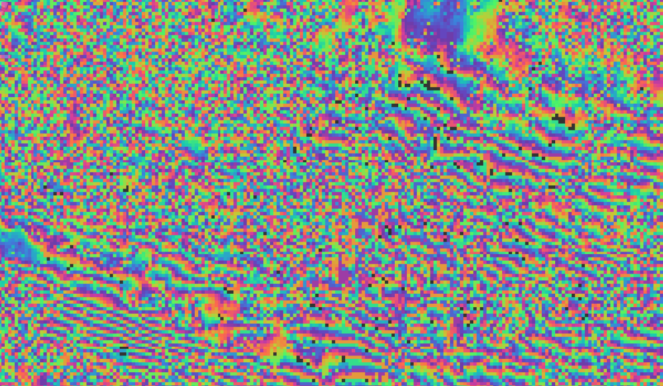
I tried following your instructions, and got the first image.
It is better than before, but still the fringes are not connected. I used goldstein filtering with filter exponent 1.0, fft size 128, and window size 5. Do you have any more ideas to improve it further?
@mfoumelis If i understand you correctly, it is not possible to use range and shift correction in the Graph Builder? I tried to use them after Backgeocoding with Output Dereamp enabled, and my computer was stuck at processing the scene for quite some time (same experience as jacky had). So it is mandataroy to first save the product after Backgeocoding, and then you can apply the shift correction? Isn’t that somewhat unpractical. I will try to solve this by creating two separate Graphs.
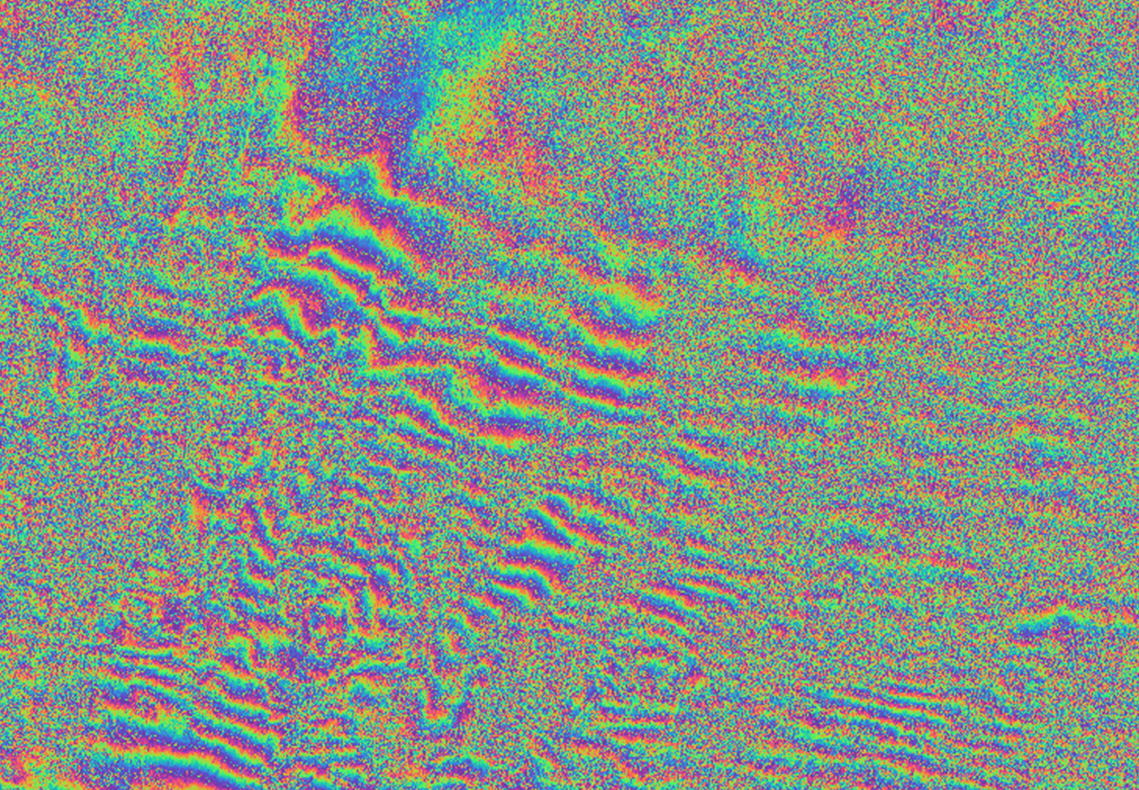
The results looks fine. Missing spatial continuity results from loss of coherence (InSAR property) and not to any processing issue. You can heavily filter or mutlilook to receive optically more pleasing effect, but especially in that case (dense fringe pattern) you most probably loose information by averaging/generalizing fringes.
Yes, currently you cannot apply range and azimuth shift subsequently within the graph builder. The problem is that each operator is reading and writing the data in a different way (by column for range and by lines for azimuth), so the output of one cannot be the inputs of the other unless full processing is done and the product is saved on disk.
In fact, our developers are trying to find a workaround for this issue, which should be solved in coming releases.