This topic has been well covered by this forum, but I would really appreciate some clarification and verification of my current thoughts (apologies for the length).
I have been trying to radiometrically normalize the effects of incidence angle on width swath IW Sentinel-1. The goal would be to determine what are the effects on crop returns in the near range compared to the far range. I will try to be as clear as possible what I mean by this, and what tools in SNAP I have tried to use. This would be the radiometric normalization of the changing incidence angle across the field of view of the sensor in the range direction. This is different from the radiometric normalization of terrain effects utilizing local incidence angle derived from the SRTM DEM. I realize now that these normalizations are different (the realization that even though you normalize using local incidence angle, IN GENERAL the local incidence angles used in the normalization will be smaller in the near range and IN GENERAL will be larger in the far range). I was missing this earlier and it caused me some confusion.
Given that, starting with using the Range Doppler Terrain Correction tool, selecting Radiometric Normalization option, this tool should take the backscatter in Sigma0 or Intensity and do a correction for local terrain effects on incidence angle using the equation in the help:
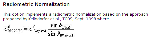
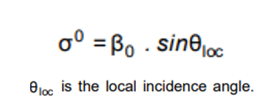
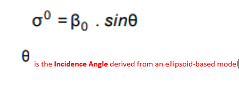
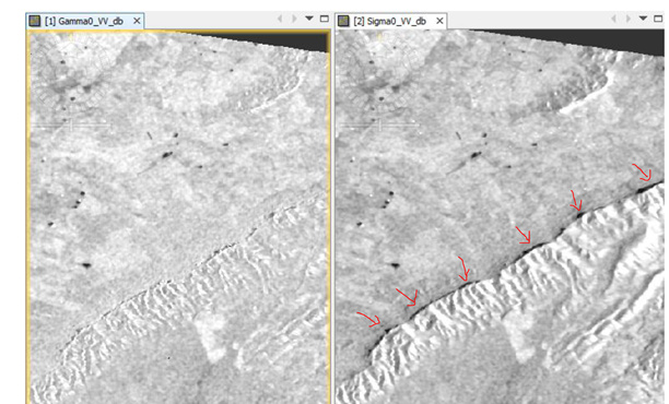
If you input Intensity, the tool will create a Sigma0, and depending on the option in the Radiometric Normalization, use local incidence angle from DEM, projected local incidence angle from DEM, or incidence angle from ellipsoid. The tool presumably will create a virtual band that has that math equation defining the correction using the DEM local incidence angle, the ellipsoid incidence angle, and the Ellipsoid based Sigma0 backscatter input. My intuition tells me that the Sigma0 band created by this tool should be the same as created by the Calibration tool. This doesn’t seem to be the case. I can’t explain why. In addition, the equation that defines the local incidence angle normalized virtual band does not match the equation from the help (I am not great with math so I could be wrong about this). Finally, it seems to me the 2 options that use local incidence angle and projected local incidence angle never use the ellipsoid incidence angle, which is the whole point of the correction (or so I think). The results of using projected local incidence angle have 2 Sigma0 bands, no incidence angles, and no virtual bands. The results of using local incidence angle and ellipsoid incidence angle produce Sigma0, incidence angles, and virtual bands describing the normalization correction. So my question is: what exactly is the Range Doppler tool doing, in that I have such a hard time understanding going from a simple equation that relates ellipsoid incidence angle, DEM local incidence angle, and Sigma0 backscatter, to the actual results that the Range Doppler tool outputs. So I need help understanding the outputs of local terrain correction tool, but that isn’t my main issue as I have illustrated to begin with (more of a side problem once I realized the difference between local and overall range normalization). The different outputs from range doppler when using radiometric normalization, along with the virtual band equations are shown below. Wouldn’t local terrain radiometric normalization always need ellipsoid angle and local DEM angle?
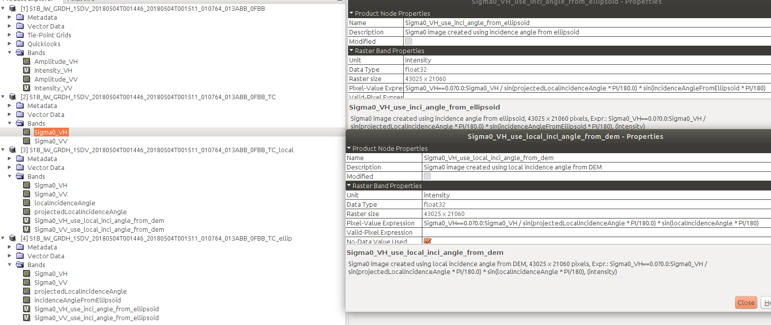
From top to bottom, input product, RD_TC with projected local DEM, RD_TC with local DEM, RD_TC with ellipsoid. Note the equations for the 2 with virtual bands.
To do over range radiometric correction, you need to model the relationship between the target surface characteristics and the incidence angle of the incoming radiation, so that a proper compensation factor can be applied (different targets respond differently at varying incidence angles). What clued me in to this was this paper:
Section 3.8 on local terrain correction normalization, and Section 3.9 on over range incidence angle normalization. Here the author presents a cosine correction with a default factor of 2.
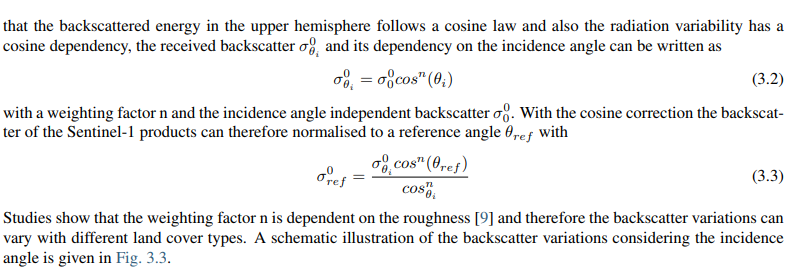
That factor would change depending on the model between target and incidence angle interaction. So, do tools exist in SNAP to perform this kind of over range normalization, even in a naive way using the same weighting factor for the entire scene. Would using the approach in the paper by using band math to manually do all the equations be a reasonable way to accomplish this? Is there something I’m missing or is the approach presented in the paper even the right way to accomplish this task?
In summary my questions are:
Am I thinking about the difference between over range incidence angle rad. correction and local terrain incidence angle rad. correction?
What are the outputs from the Range Doppler Terrain Correction (with radiometric norm option), tool, why does Sigma0 output from it not equal the Sigma0 output from Calibration. Why do some options for radiometric norm output virtual bands (local dem, ellipsoid) and some don’t (projected local dem)? Why do the equations in the virtual bands not match with the equation in the help? Why do the equations not always involved the ellipsoid angle, as that is the thing we are correcting from to get to local terrain angle?
Can SNAP perform over range incidence angle radiometric normalization? What is the best way to accomplish this if not?
Sorry for the post, but I thought it best to be clear as possible as the term radiometric normalization gets used a lot in different contexts. I have questions about when Speckle Filtering should be done but I will leave that to another (much shorter) post!