Hello all,
Where we can find the exact incidence angle of each sentinel image? Can you give me a directory in the image folder?
Thanks in advance
hello,
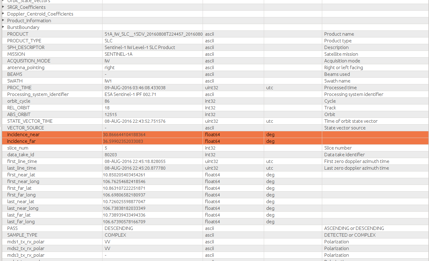
The incidence angle layer of the image is located under tie-points Grids as shown in the image below.

Also, you can go to metadata, under metadata folder and find the values for near and far range of incidence angle.
2 Likes
Thanks. However, I now opened one of them and the incidence min and max angles are 15 and 49!!! it is too much! Isn’t it? I am using a paper as my model and they used incidence angle as a criteria for using HH or HV. Lets say a rule like this: if the incidence angle of an image is more than 30 and the wind speed is more than 2 m/s use HV instaed of HH. So with this large range (15-49) what should I do and how can I go through these rules. Should I make an average! Does it make sense?
Thanks for your reply in advance
The incidence angle of SENTINEL-1 wide swath mode varies between near and far range (15-49 degrees). This is why we need to set a reference incidence angle.
In order to correct for the wide incidence angle, we need to do incidence angle normalization. Most of the authors, suggest that the incidence angle should be normalized between 30 and 35 degrees. Take a look at the paper below:
Also, in SNAP you can perform radiometric flattening that corrects the radiometric distortions.
This tool in SNAP is based on the following article posted by ABraun.
1 Like
I think you have to consider yourself in a rather fortunate position, because you have a very wide swath product (this also means with a large range of incidence angles - this is not a bad thing, it’s just a consequence of the wide swath) and dual pol HH+HV (so more information than in single pol product - this is a good thing).
I don’t know the specific task you need to solve, but some generic approaches would be:
- apply your analysis to each one of the polarimetric channels (the whole images), and then somehow merge the results in a single layer. In the merging, for each pixel you may want to give more weight to one pol or the other depending on the incidence angle of that pixel, as per your rules.
- choose one pol (whichever pol you think is going to give the best results), and apply your analysis to that pol only.
Well, I did Radiometric flattening on my data now that I open it in SNAP I cannot find where to see the incidence angle. I just need a single number for each image polarization. When I opened it in SNAP where can I find the incidence angle it is not like the original image right now. Could you please give me the directory for this new one?
Thanks in advance
HI marifo,
To be honest, I have never used the radiometric flattening for normalizing the incidence angle. I do this procedure using programming language following the guidance of the article i posted here. I set the reference incidence angle to be 35 deg and perform the task using the equations provided in the article.
sorry, but i cannot be more helpful.
Maybe @ABraun can explain a bit more about radiometric flattening in SNAP.
Radiometric terrain flattening is meant to be used over land with terrain relief. You are working over the ocean where the situation is very different, so a different correction is needed.
I do not work over ocean it is close to a bay, but I am studying little subarctic lakes! By the way I need just one number as an incidence angle to put in my formula.
The problem with SAR images acquired under wide incidence angle is that as the incidence angle gets wider, the brightness of the images gets progressively darker. This can be misleading when doing image interpretation. Hence, we need to adjust the brightness for the whole image.
The article I posted above, explains this effect very well and it provides all the necessary equations to correct for the wide incidence angle. Most of the authors suggest a reference angle to be between 30-35 deg. So, at the end you will have a new incidence angle of 35 deg.
1 Like
Isn’t this the case only if the scattering from the target is not isotropic? Ocean is a good example of directional scattering.
Yes you are right.
In ocean, for instance, we may need to identify different phenomena such as oil slick. If oil slick happens to be at the far range of the SAR image, it will appear darker(compared to what we expected the backscatter intensity from the oil spill to be) making the visual interpretation and oil spill identification harder.
incidence angle normalization is very important when doing classification (marifo mentioned about arctic lakes). If we do not correct the incidence angle when doing, lets say, sea ice types classification, same sea ice types located in both short and far range of the image will exhibit different backscatter signature increasing the misclassification error.
Is there a way to export these SAR incidence angle bands into usable datafiles? I’m looking for something like a CSV with three columns: “latitude longitude incidence_angle”. This would be used for inferring of 3-d surface displacements from LOS measurements, where multiple satellites in descending and ascending orbits can be used to calculate 3-d vectors. Thanks!
Export incidence angle per pixel
In your case it’s possible to export the incidence angel as *.csv file
Thank you!
Do you know, or anyone:
Would exporting as a netCDF-4 format be usable in GMT? Does anyone know how to export a .grd format?
SO you can find the incidence angle for each pixel for SAR imagery in snap while pre-processing the sar image. I am explaining this in simple step-wise manner.
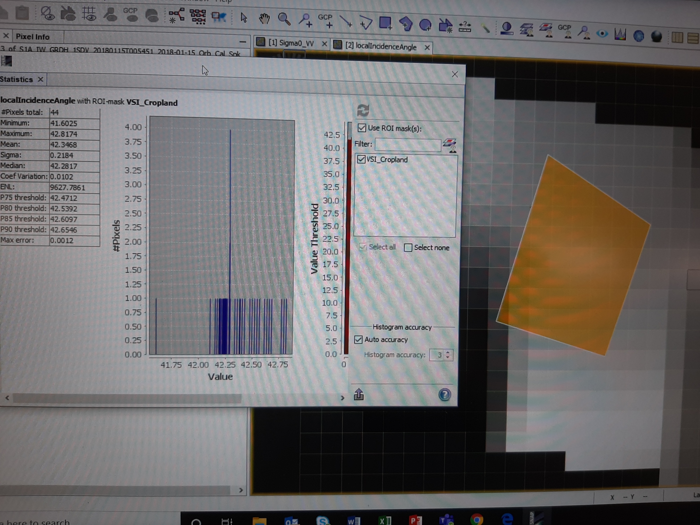
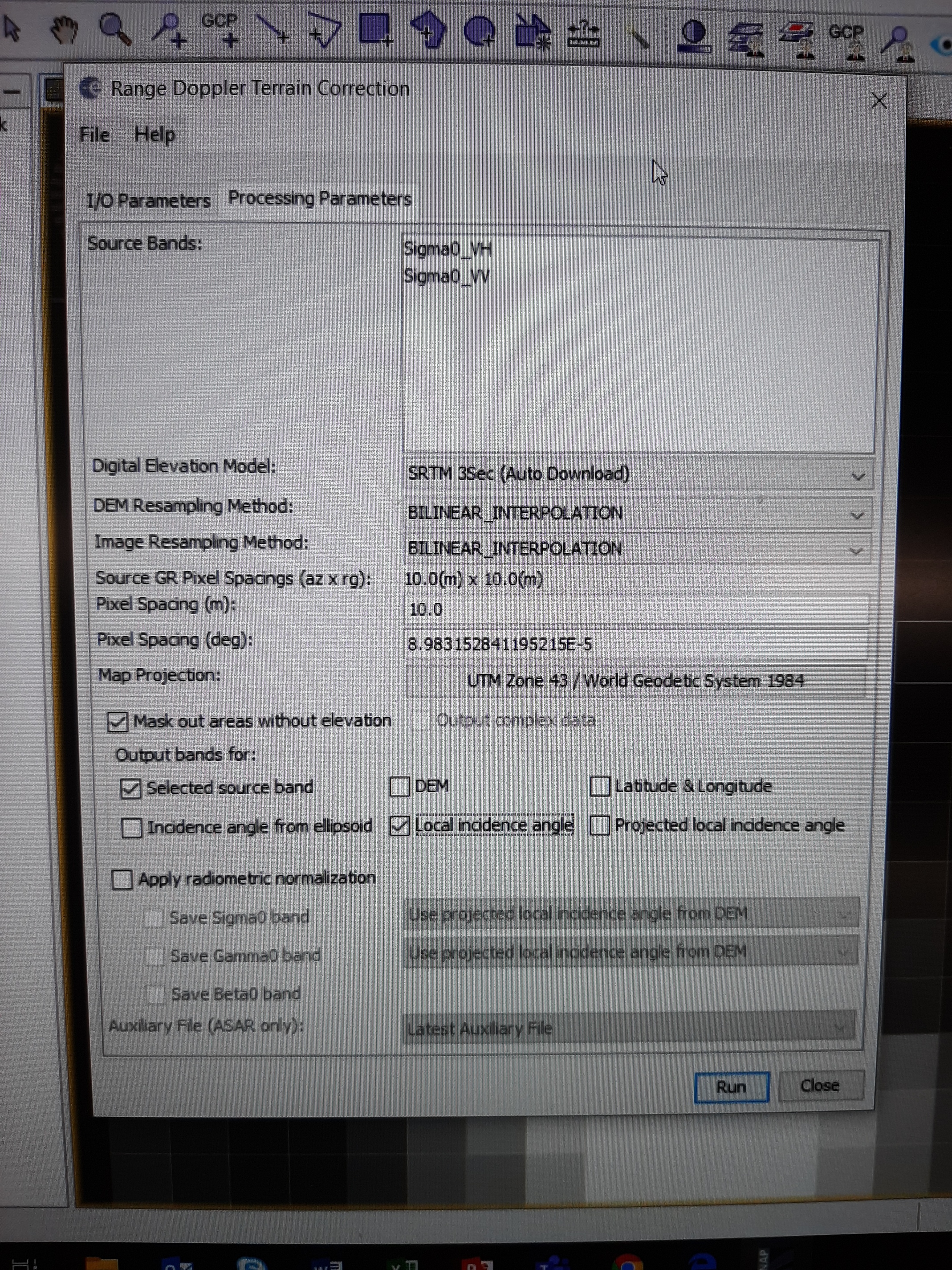
RADAR-Geometric correction-Terrain correction-Range doppler terrain correction-tick local incidence angle option-apply correction-open processed band-open incidence angle-click on pixel info-or import shapefile of your area and select Analysis-statistics

3 Likes
Hi johngan, I am recently trying to do this incidence angle normalization using the equation in the article you recommended. But I am confused. Could you please help me out?
As you said, as the incidence angle gets wider, the brightness of the images gets progressively darker, which means a smaller backscatter (db) for larger incidence angle (for example 40 degree). Since cos(40degree) is smaller than cos(35degree), which means when applying the equation 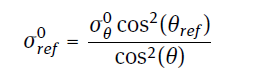 , backscatter for a new incidence angle of 35 degree could be even smaller! Is that reasonable? I am expecting it to be bigger.
Hi,
First of all, i would like to ask you what your area of interest consists of. Is it flat, vegetated or the surface contains a rough terrain.
It is true that when you look at the whole swath of a SAR image (IW mode) where the incidence angle range between 29 and 40 deg range, you can observe this effect especially in flat areas (water or sea ice). Hence, in that case, it’s important to apply incidence angle normalization.
If the SAR image acquired over an area of uneven ground (rough terrain, or trees) then this effect of incidence angle is not as evident.
There are two different methodologies that are widely used for incidence angle correction.
1. Cosine square law
This method is the one you posted. This model is based on the assumption that the amount of backscatter intensity from a surface follows a cosine law. This means that this type of surface causes a diffuse reflection of the signal (the energy is scattered in all directions).
2. linear model
For this method a linear model (1st order) is fitted between the incidence angle and the backscatter
The equation is the following: σ (35, t) = σ (θ, t) − β(θ − 35)
Where σ (θ, t) is the backscatter intensity, β is the coefficient derived from the linear modelling, θ is the incidence angle and 35 is the value we want to correct the incidence angle for.
In terms of what method needs to be used, it depends on your area of interest. If the area of interest consists of trees and terrain then cosine square law is more appropriate. Research shows that SAR signal emitted under high incidence angles (above 35 deg) does not easily penetrate through trees or vegetation. While microwaves in lower incidences angles penetrates more trough vegetation
If your area of interest is completely flat then the linear model is more appropriate.
4 Likes
Hi Johngan,
Thank you so much for the very detailed explanation. This is very helpful.
Yes, I am working on ices which are flat. i will try the linear model.
Thanks!
Hi
I was looking for a way on how to derive the local incidence angle per pixel for a Sent1 image and I found this conversation. I was wondering if we have to apply Range Doppler Terrain Correction or any other preprocessing tools before we can get the incidence angle?
Thank you