Thank you for your sincere help, I get some inspiration for your patient answer,
The lookdirection of Sentinel-1 is Right only? This parameters can not be find in XML documents.
The procedure of deburst for Sentinel-1 applies the pixel offset informaton or based on the coregistration methods?
Thanks! You are right, I have done it.
Just for confirmation, incident angle normalization should be taken into account when working with images with a wide swath in the range direction? If a study area has an increase of incident angle of few degrees it is not that relevant?
If working whith a time series with images with the same acquisition geometry, then the effect is alo less relevant that if working with images acquired in asc and desc direction?
M
Hi! Has anyone implemented incidence angle normalization in snappy? I haven’t been able to find examples of this in the forum. I am trying to estimate soil moisture by combining S1 backscatter and NDVI. Thanks!
basically, it is a combination of radiometrc calibration (to Beta0) and Terrain Flattening (produces Gamma0).
The first step is demonstrated here: http://remote-sensing.eu/preprocessing-of-sentinel-1-sar-data-via-snappy-python-module/
local incidence angle and incidence is different?( Wagner, 1999a) used incidence angle
The difference is described here: Radiometric & Geometric Correction Workflow
Hi, ABraun, about this answer. I have a question. Why not just do a radiometric calibration (to Gamma0) instead of combining of radiometric calibration (to Beta0) and Terrain Flattening (produces Gamma0)?
The answer is given by @eyeinsky here: Gamma0 only corrects for the global incidence angle (ellipsoid) while Gamma0 producced by Terrain Flattening corrects for the local illuminated area (topography):
It is explained here why we need Beta0 first: Radiometric & Geometric Correction Workflow - #71 by ABraun
ABraun, I read the link you gave me. This knowledge has been very helpful to me. And I am doing Sentinel-1 preprocessing recently. It’s a workflow. The data type is GRD. I try to be as detailed as possible. I’d like you to point out some shortcomings in my process. Thanks!
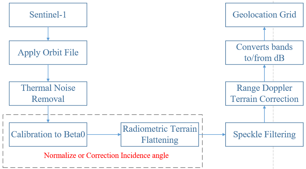
Looks good to me. What is the purpose of Geolocation Grid?
The Geolocation Grid is Geocoding. Because I need to give the image geographic information, such as latitude and longitude. I want to show my results on the map. The path of the tool is Radar–>Ellipsoid Correction–>Geolocation-Grid.
But this is already achieved by Range Doppler Terrain Correction.
If you need latitude and longitude as separate bands, you can simply check this box
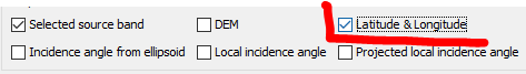
If you simply need geocoded data, RD Terrain Correction is sufficient.
I just did this experiment, and it’s a really quick way to do it. But I had the same problem with Radiometric Terrain flatting and Range Doppler Terrain Correction. The problem is the choice of the Digital Elevation Model. In Radiometric Terrain flatting, the Model I used was GETASSE03 (Auto-Download). If I use any other model, I’ll either get the following error, or the result will be all black. And in module Range Doppler Terrain Correction, I haven’t chosen a suitable DEM model yet. Using SRTM 1Sec or 3Sec will cause the following error.
So my question is, is there any standard when choosing DEM model to correct? For example which model to use under what circumstances.
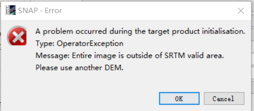
You usually use the best available, but SRTM (1Sec is 30m, 3Sec is 90m) does not cover the entire world.
You can manually download ASTER or AW3D30 and use it as an external model instead. Or you can use one of the other Auto Download DEMs, but they are not of great quality. Depends on the topography in your area.
Ok, thanks for your help.
The terrain-flattening actually corrects for the local illuminated area, not an angle. The angle is often used as a proxy for the area, but it is an imperfect proxy, and I don’t recommend using it if you have access to the better direct area estimate.
1 Like
you are right, thank you. I corrected my post above.