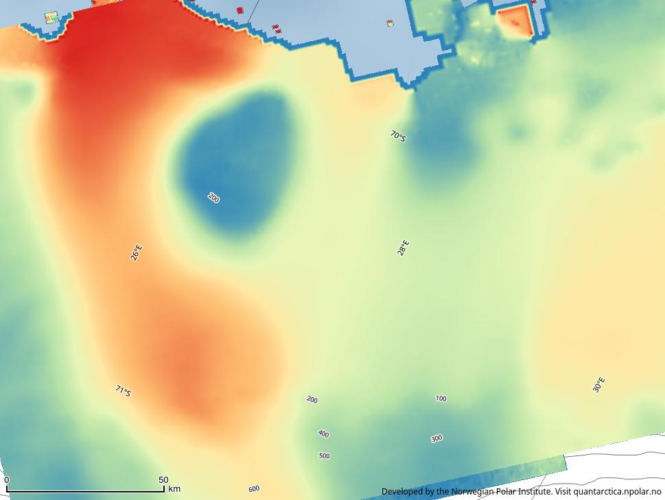
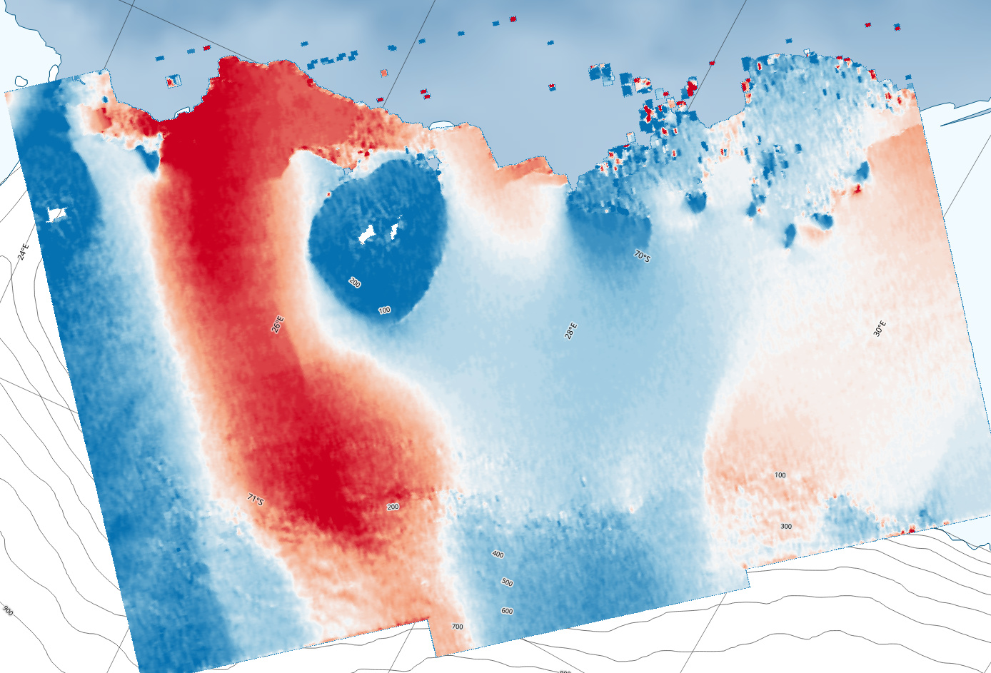
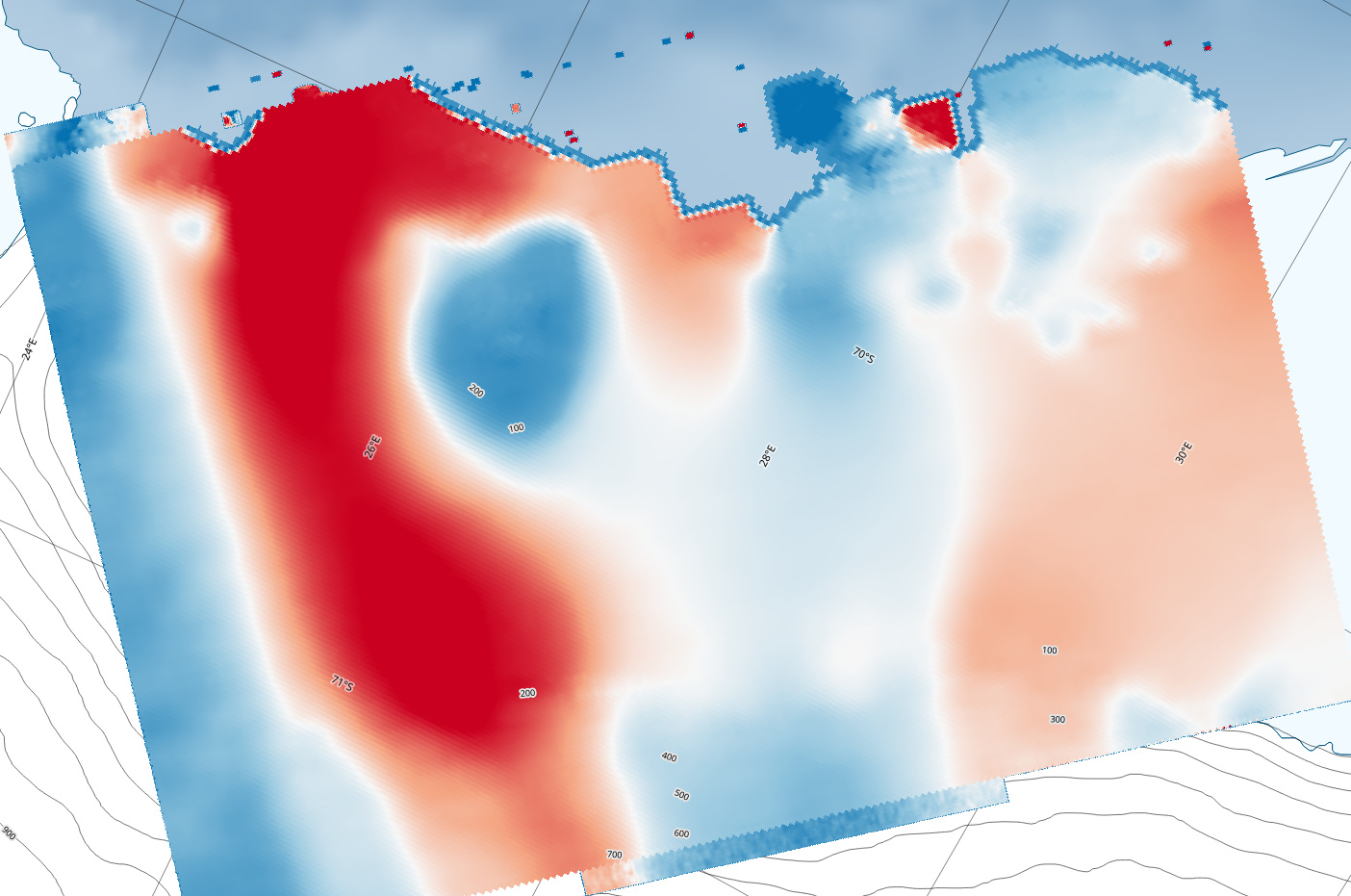
To work at finer resolution, it is desirable for me to work using SLC images instead of GRDH. Both are usable in the offset tracking tool. In the images below, you can see the geoprojected results from SLC (left) and from GRDH (right) products on the same date. Don’t pay attention to the floating numbers on the map. However, you can see that though the overall pattern is similar, the absolute values are quite overestimated in one case (or underestimated in the other). (you can click on each image to make it bigger)
This really made me worry about the consistency of the algorithm and may lead to totally different results if used by other scientists (especially glaciological modelers). We are really far from confidence range.
In effect yes. Did you detect the SLC to get rid of the phase before offset-tracking (sorry I don’t remember if the module accepts complex data as input)?
Just a potential important info. We may think that the problem is related with the fact that in my non GRD products, the range spacing is proportional to echo delay instead of range spacing proportional to distance from nadir along a predetermined ellipsoid in GRD products.
If it was the case, the offset in the SLC images would have been overestimated instead of underestimated as it is the case here.
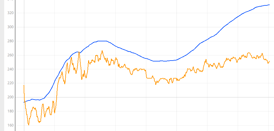
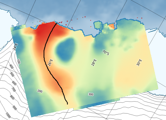
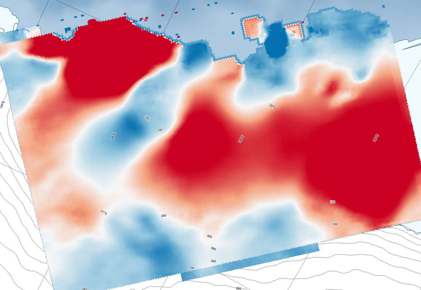
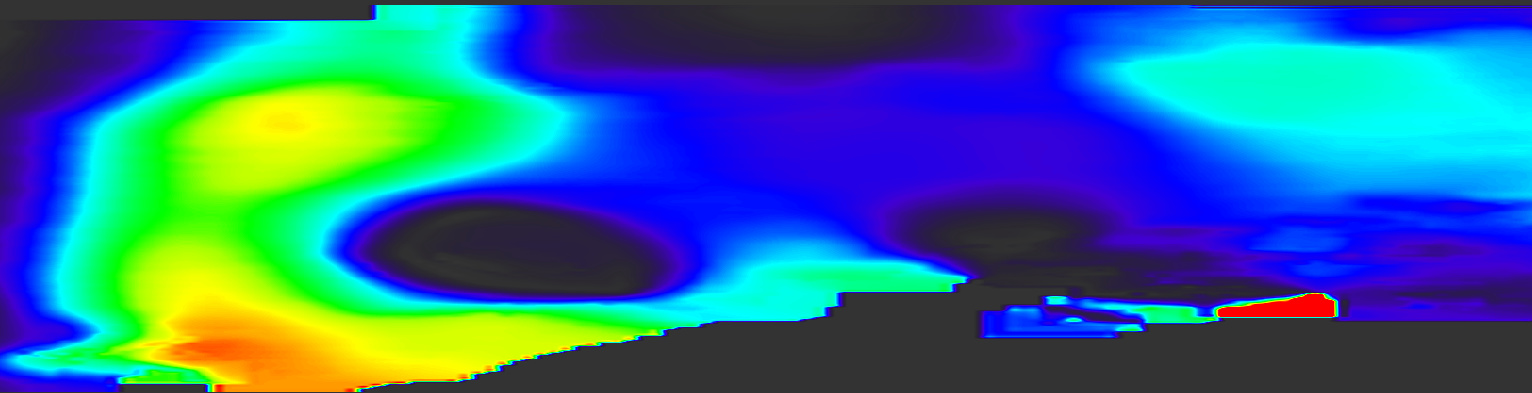
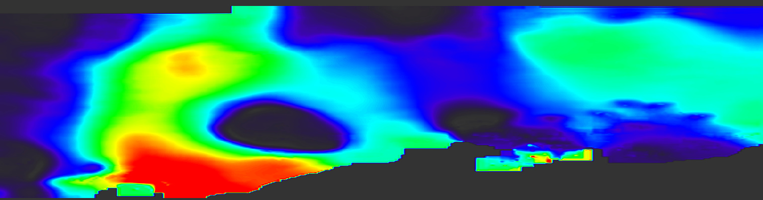
In addition, it would also mean that the problem is related to the range direction (and not the azimuth direction). However, by unlocking the “debugging bands” in SNAP, we can have access to the azimuth and range shifts. We you analyze them, the difference is present there too.
Azimuth shifts (left = SLC, right = GRD). The difference is highly visible on the right part of the image.
Note that the colorbar is identical for both images.
Related to the SLC to GRD operation, I have another question. I understand that the projection from slant range to ground range makes the image shorter. However, I don’t really understand why SNAP is resampling the image ? My image in slc is composed of 65121x13107 pixels whereas the grd image is 52779x13107. Why not just keeping the resolution of the input image ?
The input image in in radar coordinates and it’s pixel spacing on the ground changes between near- and far-range. GRD stands for Ground Range Detected.
Try ellipsoid geocoding your homemade-GRD so that it is more similar to the actual GRD.
edit: I also remembered that there are some issues related to multilooking TOPS-data that could conceivably affect the issue, as currently the operator does not do deramping. @jun_lu can perhaps comment more.
edit2: The deramping issue should only affect phase, so it should play no role here.
I am sorry, I do not understand in which purpose I should do it.
Reminder :
Offset tracking on SLC : result(1)
Offset tracking on GRD : result(2), anormaly different from result(1)
Offset tracking on home-made GRD : result(3), quite similar to result(2) and thus anormaly different from result(1)
When someone requests velocity fields on a specific area, I should not worry about which data type I use, since the SNAP module can use both. Still it gives me different results.
Nevertheless, velocity fields produced using GRD products is more coherent with velocity fields I occasionally find in scientific litterature. This is unfortunate because there are good reasons to prefer to use SLC instead of GRD.
I hope my message is clearer now. Thanks for your patience.
edit : just saw your edit. I hope @jun_lu could comment the situation
The reason for doing the ellipsoid-geocoding is to produce a product that is comparable to an actual GRD, which is also ellipsoid-geocoded. Comparing like with like enables better understanding of the issues.
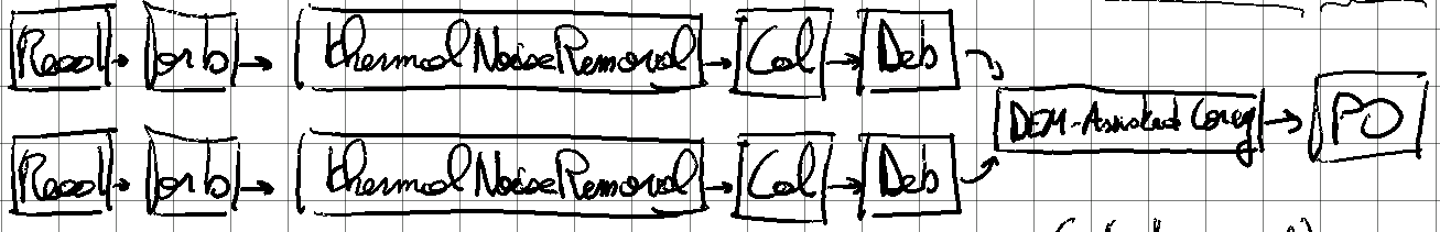
The Offset Tracking operator estimates the glacier velocity through image coregistration. It tracks the target pixel positions in two images and estimates the velocity from the range and azimuth offsets of the target positions. If SLC image is used for offset tracking, then the range offset obtained by image coregistration is in the slant range direction and it is not the offset in the ground range direction. Therefore, the velocity estimated using SLC image is not correct. You should always use GRD product for offset tracking. If no GRD products are available, you can convert the SLC products to GRD using the “S1 SLC to GRD” graph in SNAP. Then you can apply the DEM Assistant Coregistration to the converted GRD products. The graph you provided above does not have SRGR processing step in it, therefore, it does not convert the slant range image to ground range image. The images used in the offset tracking are still slant range images.
Following the thread here and having made some experiments with OffsetTracking algorithm in SNAP I’d be grateful if more details on its implementation could be given.
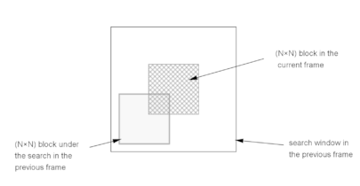
Well, it’s simply a maximization of the cross correlation. Similar to image matching techniques.
Considering two coregistered images, at given locations, you slightly moves the slave image in different directions to find a given offset (in azimuth / range) that maximizes the local cross correlation.
You can see the algorithm at line 186 here :
However, the computations are performed in the frequency domain, making things a little more complicated to interpret
Thank you for your correct reply, but actually I needed some paper on which the algorithm is based on. And how to tune the parameters in order to get better result. Cut&try is not a good option I guess.
Did you manage to resolve the difference between your offset-tracking results from Sentinel-1 SLC images vs. GRD images? I am interested in trying this method to look at landslide motion. Landslides are much smaller than the ice streams, so the highest resolution is essential.
In the ISCE software package, we always do offset tracking directly on the SLC images to maintain resolution, and as you mentioned it is better to maintain the speckle pattern.
I would love to use SNAP for speckle tracking but it is not reliable, unfortunately. Getting different results from the same image source is an absolute no way if you aim publications.
To put it simply : SNAP using GRD is a coarse feature tracking techniques, with unfortunately low accurate results. SNAP using SLC produces biased results.
Using SLC images THEN projecting is the only way to make speckle tracking.
For my usage, our institution developed some variant of speckle tracking (in C language) method and I’m currently trying to adapt it in python.
@qglaude Thanks for letting me know. I am working on an ARSET webinar training for measuring landslide deformation with SAR. I am using SNAP for the demonstration session. It sounds like I cannot use the SNAP pixel or speckle tracking function to show how it works.
Eric, do you think working on detected SLCs would be an improvement over GRDs? If I’m not mistaken implementing coherent speckle-tracking is not entirely trivial.