Amplitude. The module only reads detected images.
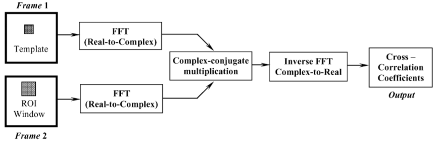
This is something of this type (maximization of ICC in fourier domain). You can get the full implemention in the SNAP Github
and
Look at the code below and use the Vincenty Inverse formula to calculate the azimuth.
GeoUtils.DistanceHeading heading = GeoUtils.vincenty_inverse(mstGeoPos, slvGeoPos);
feature.setAttribute(ATTRIB_HEADING, heading.heading1);
Is the result of the calculation the forward azimuth or the backward azimuth?
From what I remember, it is the angle from north, measured clockwise. Maybe @lveci can confirm ?
The ISCE2 GitHub page has information on installing it in Docker containers. There is some other information about setting it up. If you use Anaconda, it can only install the official point releases, such as the v2.3.3 released in April 2020.
What is the relationship between the positive/negative offsets calculated by the offsets tracking operator and the satellite? ( For example, in the PS/SBAS results calculated by StaMPS/MTI: if the master predates the slave, positive phase implies movement away from the satellite.)
To my understanding, the offset tracking identifies horizontal movement on a surface, so I would not expect negative values at all.
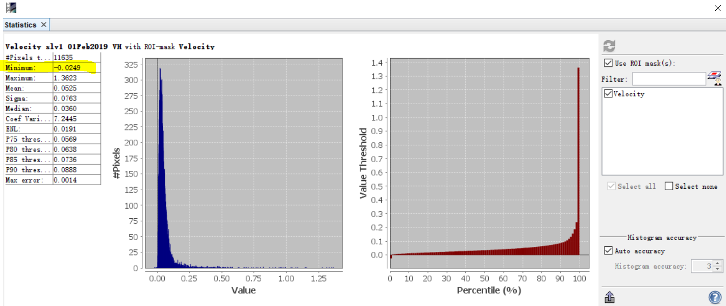
It’s a long time issue but, for some reasons, negative values are present in the velocity band.
1 Like
wasn’t aware of that. Is it related to the oversampling issue you once introduced?
No it is older than that. It is maybe related to resampling issues at boundaries (just trying to guess).
There are indeed cases where the POT calculation result is negative (as shown in the figure below).
I have another question: Is the correct LOS direction from the ground to the satellite or the satellite to the ground?
Neither of both. It’s the magnitude of the two components of the horizontal displacement between your 2 images.
1 Like
@qglaude, Since I want to convert the ground range and azimuth offsets calculated from the single pass image to LOS or vertical. So I need to figure out the direction of LOS. The direction of LOS in different papers seems to be different (opposite), which confuses me.
@SUN-Ravenclaw. Unfortunately, you cannot. The problem is underconstraint. I mentionned it quickly here : https://ieeexplore.ieee.org/document/9138726
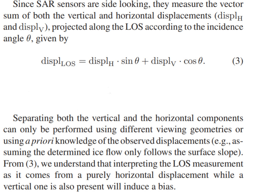
Because SNAP offset tracking module works with GRD images, it assumes pure horizontal displacements. Over iceflow, this is not far from the truth, but you have to be careful if you want to determine vertical displacement using the offset tracking of SNAP. It exists some way to “trick” SNAP into computing PO on SLC images (and so getting true LOS displacements), but it is a bit technical …
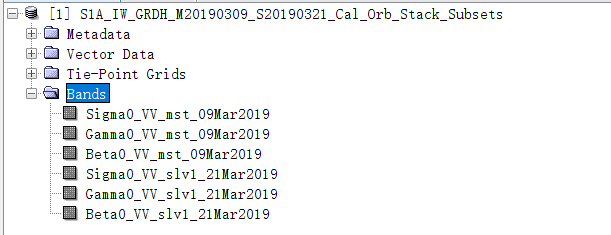
@qglaude Calibrate Operator can get three different intensity data of Sigmma0, Gamma0, Beta0. Can I use Beta0 to calculate the pixel offset in the LOS direction?
@SUN-Ravenclaw Offset tracking uses GRD images, meaning that the displacements are computed in the horizontal plane (not the LOS direction).
Are you planning to use the Calibrate Operator on SLC images before using Offset Tracking? It is indeed possible. Why do you want to use Beta0? If so, be careful to use the same relative orbit.
I have been using GRDH data to achieve pixel shifting. Because GRDH data is dual polarization, so I use Calibrate Operator to get VV polarization data.
In Calibration, I can choose to output Sigma0, Gamma0, or Beta0.
Isn’t Beta0 the intensity of the slant range direction?
These measures are highly redundant, so I think Sigma0 (defined as radar cross section) is sufficient for offset tracking. Beta0 does not incorporate the global incidence angle of the product, so I would consider it less suitable.
Does this mean that we can use the S1_GRD_FLOAT collection of GEE for offset tracking? But will these terrain corrected data in GEE affect the final result? In SNAP, the terrain correction is performed after offset tracking. Thank you.