Hello,
I am working on Sentinel-1/TerraSAR-X SAR SLC images, and I encountered a problem during my work. This is not a bug or a crucial issue, but I think it would be worth adding an information message about it. For my research, I have to use images terrain-corrected with different pixel sizes. Everything works perfectly when I am doing it in SNAP, but as I use many images, I have to use gpt. In SNAP, if the pixel spacing in meters is changed, the pixel spacing in degrees is automatically calculated, and vice versa. Using gpt, if the graph imported was created in SAP with SAR data opened and then saved, an initial pixel spacing in meters and pixel spacing in degrees are already loaded. When using this graph for a different pixel spacing, if only the pixel spacing in meters is entered, the pixel spacing in degrees is not calculated, which is totally logical. However, if the two values do not match, the pixel spacing in degrees is used. This can lead to a disturbing situation because the pixel spacing written in the metadata corresponds to the entered input. Still, the actual pixel spacing is the one that was previously written in the .xml file, using the pixel spacing in degrees. Therefore, I think an Information message when using Range Doppler Terrain Correction in gpt might be helpful, explaining that the pixel degrees in meters and degrees have to be entered. Furthermore, a Warning message for when the pixel spacing in meters and the pixel spacing in degrees does not match would really be helpful too, to explain that the output will be obtained using the pixel spacing in degrees, no matter what is written in the output metadata.
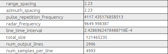
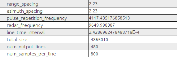
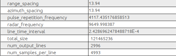
Here is the metadata for four examples to prove my point. The input data is a TerraSAR-X image, the initial values proposed by SNAP for the Terrain Correction are 2.23m/2.0032430835865326E-5°, and I wanted to change it to 13.94m/1.252251506062613E-4°.
XML Input : 2.23m and 2.0032430835865326E-5°
XML Input : 2.23m and 1.252251506062613E-4
XML Input : 13.94m and 2.0032430835865326E-5°
XML Input : 13.94m and 1.252251506062613E-4
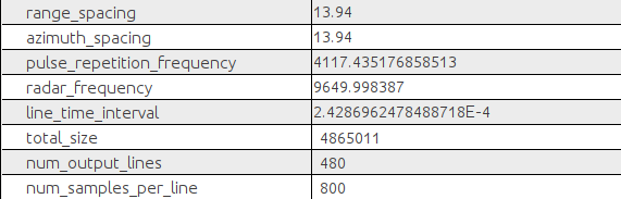
As explained, the pixel_spacing correspond to the input pixel spacing in meters, but the actual pixel spacing (linked to num_output_lines and num_samples_per_lines) depends on the input pixel spacing in degrees.
Here is the bash file I used :
#!/bin/bash

set -e

#1 To define

pixelSpacing=13.94
degreeSpacing=1.252251506062613E-4
pixelSpacingName="${pixelSpacing//./$'_'}"
Path_Data_Traites=XXXXXX
Path_Data_Traites_Subset=XXXXX
Path_Traites_XML=XXXX
Name_txt="XXXXX.dim"
Subset='POLYGON ((  X X, X X, X X, X X, X X))'

#2 Automatic
echo $Subset
Path_Data_Traites_Subset_Folder=${Path_Data_Traites_Subset::-1}
echo $Path_Data_Traites_Subset_Folder
mkdir -p $Path_Data_Traites_Subset_Folder

#3-Extract date & run GPT
date
k=0
echo $Path_Data_Traites
for i in $(ls -1 $Path_Data_Traites*.dim)
do
((++k))
echo $i
n=${i##*XXX/}
n=${n::-4}
echo $Path_Data_Traites_Subset$n$Name_txt

XXX/gpt $Path_Traites_XML -Pinput1=$i  -Poutput1="$Path_Data_Traites_Subset$n$Name_txt" -PSubset="$Subset" -PpixelSpacing="$pixelSpacing" -PdegreeSpacing="$degreeSpacing"
date
echo $k
done
And the XML file :
<graph id="Graph">
<version>1.0</version>
<node id="Read">
<operator>Read</operator>
<sources/>
<parameters class="com.bc.ceres.binding.dom.XppDomElement">
<file>$input1</file>
</parameters>
</node>
<node id="Subset">
<operator>Subset</operator>
<sources>
<sourceProduct refid="Terrain-Correction"/>
</sources>
<parameters class="com.bc.ceres.binding.dom.XppDomElement">
<sourceBands/>
<region>0,0,0,0</region>
<referenceBand/>
<geoRegion>$Subset</geoRegion>
<subSamplingX>1</subSamplingX>
<subSamplingY>1</subSamplingY>
<fullSwath>false</fullSwath>
<tiePointGridNames/>
<copyMetadata>true</copyMetadata>
</parameters>
</node>
<node id="Terrain-Correction">
<operator>Terrain-Correction</operator>
<sources>
<sourceProduct refid="Read"/>
</sources>
<parameters class="com.bc.ceres.binding.dom.XppDomElement">
<sourceBands/>
<demName>SRTM 3Sec</demName>
<externalDEMFile/>
<externalDEMNoDataValue>0.0</externalDEMNoDataValue>
<externalDEMApplyEGM>true</externalDEMApplyEGM>
<demResamplingMethod>BILINEAR_INTERPOLATION</demResamplingMethod>
<imgResamplingMethod>BILINEAR_INTERPOLATION</imgResamplingMethod>
<pixelSpacingInMeter>$pixelSpacing</pixelSpacingInMeter>
<pixelSpacingInDegree>$degreeSpacing</pixelSpacingInDegree>
<mapProjection>GEOGCS["WGS84(DD)",
DATUM["WGS84",
SPHEROID["WGS84", 6378137.0, 298.257223563]],
PRIMEM["Greenwich", 0.0],
UNIT["degree", 0.017453292519943295],
AXIS["Geodetic longitude", EAST],
AXIS["Geodetic latitude", NORTH]]</mapProjection>
<alignToStandardGrid>false</alignToStandardGrid>
<standardGridOriginX>0.0</standardGridOriginX>
<standardGridOriginY>0.0</standardGridOriginY>
<nodataValueAtSea>false</nodataValueAtSea>
<saveDEM>false</saveDEM>
<saveLatLon>false</saveLatLon>
<saveIncidenceAngleFromEllipsoid>false</saveIncidenceAngleFromEllipsoid>
<saveLocalIncidenceAngle>false</saveLocalIncidenceAngle>
<saveProjectedLocalIncidenceAngle>false</saveProjectedLocalIncidenceAngle>
<saveSelectedSourceBand>true</saveSelectedSourceBand>
<outputComplex>true</outputComplex>
<applyRadiometricNormalization>false</applyRadiometricNormalization>
<saveSigmaNought>false</saveSigmaNought>
<saveGammaNought>false</saveGammaNought>
<saveBetaNought>false</saveBetaNought>
<incidenceAngleForSigma0>Use projected local incidence angle from DEM</incidenceAngleForSigma0>
<incidenceAngleForGamma0>Use projected local incidence angle from DEM</incidenceAngleForGamma0>
<auxFile>Latest Auxiliary File</auxFile>
<externalAuxFile/>
</parameters>
</node>
<node id="Write">
<operator>Write</operator>
<sources>
<sourceProduct refid="Subset"/>
</sources>
<parameters class="com.bc.ceres.binding.dom.XppDomElement">
<file>$output1</file>
<formatName>BEAM-DIMAP</formatName>
</parameters>
</node>
<applicationData id="Presentation">
<Description/>
<node id="Read">
<displayPosition x="30.0" y="131.0"/>
</node>
<node id="Subset">
<displayPosition x="535.0" y="132.0"/>
</node>
<node id="Terrain-Correction">
<displayPosition x="226.0" y="134.0"/>
</node>
<node id="Write">
<displayPosition x="897.0" y="115.0"/>
</node>
</applicationData>
</graph>