you should find most of it in the product description
I don’t work with RS2 data but I guess beam mode is the sar backscatter and incident angle range is a kind of tie-point grid for calibration / normalization purposes.
Thanks for the info.
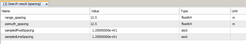
I need to report the resolution (m) of SLC radarsat2 raw data. On the forume i ve seen a discusdion saying that resolution is slightly higher than “az.spacing x rg. spacing”. Should i ignore it and go with az.spacing x rg.spacing (2.079×1.331) as the resolution?
On the other hand, it s assumed that the SAR imagery i m working on has a resolution of 2.5 m.
I m wondering how did we end up with 2.5 m of resolution?
Your range spacing is in slant range - if you convert to ground range you are probably going to end up with more or less equal pixel spacing in both directions (a bit over 2m).
So az. range remains constant while rg.spacing changes?
I m kindda confused when it comes to this slant azimuth range to ground range. Would you plz explain more how the conversion is made?
Thanks again
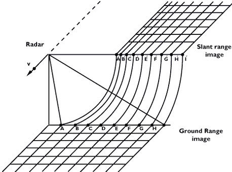
Range resolution is different in SLC mode, you have small pixels near the sensor and large ones far away (A-H).
Azimuth is the direction of flight (v). As the sensor operates at a constant velocity, all pixels have the same resolution.
If you want to get square pixels you can only have the resolution of the flight direction, because this is the smallest in v direction. Therefore you would need to adjust some of the pixel sizes in range direction according to this value.
In Table 1-3 (pages 27 and 28 out of 91) of the document linked by ABraun above you will find the information about the resolution for each mode. For SLC products, resolution is given in slant range.
In Annex A of the same document you will find the ground range resolution at near and far range for each beam of each mode.
If you want to calculate ground range resolution from slant range resolution yourself, try: res_GR = res_SR/sin(incidence_angle)
Incidence angle is a function of range, so res_GR also varies with range. You can get the incidence angles at near and far range either from Annex A, from the image metadata (fields incidenceAngleNearRange and incidenceAngleFarRange), or from SNAP.
The image is correct but I would have drawn it differently keeping the sampling constant in the slant range image. Then it would have been easier to see how range-resolution is better in far ground range than in near ground range…