Reading .dim file's metadatas without Snappy

Hi dears,

I’m really sorry for the Snappy devs, you did great job, but I don’t want to use snappy as I don’t feel sure about it… (python version issue + not stable enough in my opinion)

Till now I did my job from satellite products that have their own structures but accessible metadatas.
The issue is now that I want to implement the “Slice Assembled Sentinel-1 product” and I don’t know how to access the metadatas from this .dim assembled file as SNAP does from Java.

It’s not easy to find the snappy repo as there is a lot of repos with this name.
I found this repo but it’s an old one.
If someone got the repo of snappy, I would be glad to investigate from it.

And if anyone knows how to read .dim metadatas from Python, it would be very welcome

Thanks a lot,
Best,
Ari

The repository you found is the correct one for snappy.
But you won’t find the code there for reading the *.dim file.
The snappy library only delegates to Java code reading the content of the file.
The actual reading is done in the DimapProductReader

But you can also read the DIM file with any XML library as it contains plain XML.

1 Like

Perfect! thanks a lot for tips that DIM is XML readable :slight_smile:

Best,
Ari

Hi again dear marpet,

I’m now curious about how Snap is getting the total extent from an SLC product ?
as well as the CRS in the automatic UTM projection from Range Doppler Correction function ?

I don’t find those kind of informations from the dimap file

Kind regards,
Ari

Hi Ari,

I don’t know much about SLC products, but the extent is handled generically in SNAP and DIMAP.
In general, you know the dimension of the scene in pixels.
And you know the UTM projection, with the false-easting and false-northing information.
Also known are the easting and northing information of the reference point (usually upper-left pixel) and also the pixel-spacing is known for the scene.
With this information the scene can be located on earth.

The following is an excerpt of a DIMAP.

<Coordinate_Reference_System>
        <WKT>
             PROJCS["WGS 84 / UTM zone 45N", 
               GEOGCS["WGS 84", 
                 DATUM["World Geodetic System 1984", 
                   SPHEROID["WGS 84", 6378137.0, 298.257223563, AUTHORITY["EPSG","7030"]], 
                   AUTHORITY["EPSG","6326"]], 
                 PRIMEM["Greenwich", 0.0, AUTHORITY["EPSG","8901"]], 
                 UNIT["degree", 0.017453292519943295], 
                 AXIS["Geodetic longitude", EAST], 
                 AXIS["Geodetic latitude", NORTH], 
                 AUTHORITY["EPSG","4326"]], 
               PROJECTION["Transverse_Mercator", AUTHORITY["EPSG","9807"]], 
               PARAMETER["central_meridian", 87.0], 
               PARAMETER["latitude_of_origin", 0.0], 
               PARAMETER["scale_factor", 0.9996], 
               PARAMETER["false_easting", 500000.0], 
               PARAMETER["false_northing", 0.0], 
               UNIT["m", 1.0], 
               AXIS["Easting", EAST], 
               AXIS["Northing", NORTH], 
               AUTHORITY["EPSG","32645"]]
        </WKT>
    </Coordinate_Reference_System>
    <Geoposition>
        <BAND_INDEX>0</BAND_INDEX>
        <IMAGE_TO_MODEL_TRANSFORM>60.0,0.0,0.0,-60.0,735960.0,2473380.0</IMAGE_TO_MODEL_TRANSFORM>
    </Geoposition>
    <Raster_Dimensions>
        <NCOLS>4538</NCOLS>
        <NROWS>5042</NROWS>
        <NBANDS>1</NBANDS>
    </Raster_Dimensions>

In Coordinate_Reference_System the CRS is defined with the false-easting and false-northing besides other information.
In Geoposition we have the pixel-spacing (x:60, y:-60), the reference point (0, 0) and the easting and northing (735960.0, 2473380.0).
Finally, in Raster_Dimensions the dimension is stored of the scene.

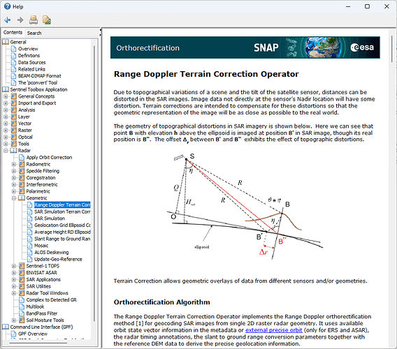
Maybe also the help about Range Doppler Terrain Correction can help you further.
1 Like

I know this is a bit of a longshot since your post was about a year ago, but I have a question. I am a new grad student trying to work with AC algorithms in python, but I have to code them first(and I am not much of a programmer). You wouldn’t happen to know how to go about converting the TOA reflectance into TOA radiance from sentinel2-1C data would you? I have code to read in whatever portion of the XML files and jp2 files I need, but I am not sure what data needs to be used for the per pixelperband and the incident angles arrays. Any and all help would be greatly appreciated.
Respectfully,
Jason