Can someone share the RCM data name convention?
What do SC30MCPA, CPB, and CPC indicates?
With regards to opening RCM scenes, I understand from the discussion that MLC can be opened in SNAP but we don’t have any solution for SLC for now. Am I right on this?
I am wondering how were you able to open the SLC product in SNAP when others are facing trouble. Are you using a different version of SNAP? Seems like you can open a 5m data but not a 30m one.
My understanding is that the RCM CP SLC has two modes: Stripmap and ScanSAR. Stripmap has higher resolutions of 3m, 5m, and 16-meter, while ScanSAR resolutions are 30-meter and above. You will see only one tiff image in the file subfolder of \imagery for Stripmap, but hundreds tiff files in ScanSAR which need to be debursted.
Currently SNAP can only read Stripmap SLC but not ScanSAR SLC. From the file name, I believe mthompson opened a 5m stripmap SLC file.
I notice that in the ScanSAR mode there are two kinds of scenes. One is a more square scene and the other is a more elongated rectangular scene that looks like an SLC but actually, it is not. The metadata claims both of them to be 30 m. What is the difference between these two scenes if the imaging mode is the same?
I haven’t been working with Radarsat ScanSAR products so far but could it be that the incidence angle differs between those two? Or do you refer to the same acquisition but at two product levels?
SNAP currently doesn’t support deburst and merge for non-ESA missions. To make it work correctly for each sensor is not a trivial amount of work. That being said, it would be good to know how much user-interest there is in this product. Ideally the satellite provider would fund the development of readers for their missions.
When you look at the ScanSAR scenes of the RCM, one is a more square scene and the other is a more elongated rectangular scene that looks like an SLC but actually, it is not. The metadata claims both of them to be 30 m. I don’t get the difference.
You have already said that but I’m trying to understand if you are talking about two images of different dates or if these two scenes have the same acquisition date.
Maybe you can share a screenshot to illustrate what you mean.
These scenes are from different dates and they are from different satellite passes. The Square one is Ascending whereas the elongated one is Descending. They both cover roughly the same area but the geometries in the elongated scene appear a bit distorted.
Thank you for clarifying. Can you please check their incidence angle in the metadata. Looks like the image on the right was acquired at a larger incidence angle and therefore has more distortion in range direction.
That could be it, the square scene spans 5 degrees closer to nadir and the other one 7 degrees in a much more shallow angle, so naturally it covers a wider strip.
I think the area is more or less the same but the distortion makes it appear stretched. When I am trying to locate ROIs in these two images, given Lat/Long corner coordinates of the ROIs, the shape of the ROIs appears to be distorted as well and not fitting around the actual area. This is not the issue when I use the Lat/Long info for the square scene. I don’t get why is this geolocationing of the ROIs going wrong with the elongated scene.
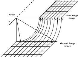
Both images are displayed in slant range geometry. The steeper the incidence angle the stronger the distortion. This is completely normal for SAR images.
You should find out what the product type is for your ScanSAR-scenes, as they are obviously different. It sounds like the elongated one could be single-look with non-square pixels, which can confuse some softwares.
@ABraun @mengdahl
I get this part of distortion at a steeper incidence angle. What is unusual is that when I try to locate my ROIs using the Lat/Long coordinates (I use my Python script code to find the ROIs in the image), it works perfectly fine with the square scene, but this doesn’t work for the elongated one.
As I said, both scenes are delivered in slant range geometry. If one of them is acquired at a steeper incidence angle, their distortion in slant direction is different. This is among the most important concepts of radar imaging.
If you apply Range Doppler Terrain Correction to both images you will get them in geocoded ground range geometry and the ROI should be of equal size for both.
@ABraun
I am not so much bothered by the shape of the ROIs but there is an offset in their positions. So when I use the Lat/long grid of the image and the UTM locations of my ROIs for the square scenes they fall in place whereas when I do the same for the elongated scenes they are misplaced. It would have been absolutely fine with me if the located ROIs were just differing in their dimensions but this is not the case.