Row/column convention for GCPs in Sentinel 1 GRD products

Hi,

I’m having a hard time figuring out the precise interpretation of the row and column coordinates of the ground control points in Sentinel 1 products that are ground range detected.

Let us consider the scene S1A_IW_GRDH_1SDV_20230418T045710_20230418T045735_048146_05C9DA_636F as an example.

The scene has 16669 rows and 26612 columns of pixels. It comes with a grid of 10×21 ground control points.

Running GDALs listgeo on one of the GeoTiffs provided shows that the convention used for row and column coordinates is PixelIsArea, which means that the coordinate row=0, col=0 of GCP_0 is in the top left corner of the very first image pixel (see the specification of GeoTiff). This is confirmed when opening the GeoTiff with SNAP:

grafik

However, the last GCP in in the first row is at position row=0, col=26611, which is the top left corner of the top right pixel:

grafik

Hence, the last column of pixels of the image is outside the grid of GCPs. I would have expected the top right GCP to be located at row=0, col=26612, so that it sits in the top right corner of the top right pixel.

The same is true for the last row of the image, respectively. So in this interpretation of the GCPs, the last row and column of the image are not properly georeferenced by the GCP grid. (One would have to extrapolate instead of just interpolating for geocoding.)

Is this interpretation correct or does the GCP at row=0, col=0 really describe the geographic position of the center of the very first pixel, as if the referencing convention would be PixelIsPoint?

3 Likes

Adding to the investigation, here is what happens when you take a Sentinel-1 GRD product (S1A_IW_GRDH_1SDV_20230418T045710_20230418T045735_048146_05C9DA_636F.SAFE), open it in SNAP and without any processing save it as BEAM-DIMAP:

For the GeoTIFF files in *.SAFE/measurements/ the listgeo tool lists the GCPs as follows:

Geotiff_Information:
   Version: 1
   Key_Revision: 1.0
   Tagged_Information:
      ModelTiepointTag (420,3):
         0                 0                 0
         26.8451672983579  66.486390503476   172.991735818796
         ...
         26611             16668             0
         20.3371741685618  65.495580215619   299.978554510511
      End_Of_Tags.
   Keyed_Information:
      GTModelTypeGeoKey (Short,1): ModelTypeGeographic
      GTRasterTypeGeoKey (Short,1): RasterPixelIsArea
      GTCitationGeoKey (Ascii,25): "Geo-referenced SAR image"
      GeographicTypeGeoKey (Short,1): GCS_WGS_84
      GeogCitationGeoKey (Ascii,7): "WGS 84"
      GeogLinearUnitsGeoKey (Short,1): Linear_Meter
      GeogAngularUnitsGeoKey (Short,1): Angular_Degree
      GeogEllipsoidGeoKey (Short,1): proj_create_from_database: ellipsoid not found
Unknown-4326
      GeogSemiMajorAxisGeoKey (Double,1): 6378137
      GeogSemiMinorAxisGeoKey (Double,1): 6356752.314245
      GeogInvFlatteningGeoKey (Double,1): 298.25722356049
      ProjLinearUnitsGeoKey (Short,1): Linear_Meter
      End_Of_Keys.
   End_Of_Geotiff.
proj_create_from_database: ellipsoid not found

GCS: 4326/WGS 84
Datum: 6326/World Geodetic System 1984
proj_create_from_database: ellipsoid not found
Ellipsoid: 4326/(unknown) (6378137.00,6356752.31)
Prime Meridian: 8901/Greenwich (0.000000/  0d 0' 0.00"E)
Projection Linear Units: 9001/metre (1.000000m)

Corner Coordinates:
 ... unable to transform points between pixel/line and PCS space

In the corresponding *.dim file, the new tie point grids are defined as follows:

        <Tie_Point_Grid_Info>
            <TIE_POINT_GRID_INDEX>0</TIE_POINT_GRID_INDEX>
            <TIE_POINT_DESCRIPTION />
            <PHYSICAL_UNIT>deg</PHYSICAL_UNIT>
            <TIE_POINT_GRID_NAME>latitude</TIE_POINT_GRID_NAME>
            <DATA_TYPE>float32</DATA_TYPE>
            <NCOLS>21</NCOLS>
            <NROWS>10</NROWS>
            <OFFSET_X>0.5</OFFSET_X>
            <OFFSET_Y>0.5</OFFSET_Y>
            <STEP_X>1330.6</STEP_X>
            <STEP_Y>1852.111111111111</STEP_Y>
            <CYCLIC discontinuity="0">false</CYCLIC>
        </Tie_Point_Grid_Info>

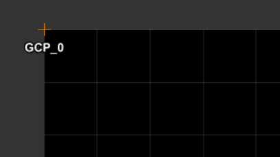
Note that OFFSET_X and OFFSET_Y are both set to 0.5 , so the first GCP in the grid should be located at pixel position (0.5,0.5), which I can only assume to be the center of the first pixel.

Extracting the latitude and longitude coordinates of the first GCP from *.data/tie_point_grids/{latitude,longitude}.img, the first GCP has longitude 26.845167 and latitude 66.48639, matching the first GCP in the GeoTiff (with a bit loss of precision).

So from the BEAM-DIMAP files, I have the suspicion that the first GCP in the GeoTIFF also should have been located at the center of the first pixel and either should have been listed as row=0.5, col=0.5 or the GeoTIFF should have raster type PixelIsPoint instead.

For completeness, here’s the first GCP as listed in the *.SAFE/annotations/*.xml files:

      <geolocationGridPoint>
        <azimuthTime>2023-04-18T04:57:10.257157</azimuthTime>
        <slantRangeTime>5.337481673596213e-03</slantRangeTime>
        <line>0</line>
        <pixel>0</pixel>
        <latitude>6.648639050347597e+01</latitude>
        <longitude>2.684516729835792e+01</longitude>
        <height>1.729917358187959e+02</height>
        <incidenceAngle>2.967662079378803e+01</incidenceAngle>
        <elevationAngle>2.646322582002259e+01</elevationAngle>
      </geolocationGridPoint>

Again, it is not clear to me here, whether the line and pixel attributes refer to the upper left corner or the center of the indexed pixels. The Sentinel-1 product specification just lists:

Name Description Data Type Cardinality
line Reference image MDS line to which this geolocation grid point applies. uint32 1
pixel Reference image MDS sample to which this geolocation grid point applies. uint32 1
1 Like

We are checking if the reference of the GCP coordinates shall be RasterPixelIsArea or RasterPixelIsPoint.

However, please consider that the GCP provided in the Sentinel-1 Level 1 products (SLC and GRD) are not designed to ensure a precise georeferencing of the product.

Precise geocoding of Sentinel-1 products require extra processing steps documented in following document:

In SNAP, the Range Doppler Terrain Correction applies such type of processing.

2 Likes

Are there any news on this?

Yes sorry for the delay

From Raster Data Model — GDAL documentation : AREA_OR_POINT may be either Area" (the default) or “Point”. This Indicates whether a pixel value should be assumed to represent a sampling over the region of the pixel or a point sample at the center of the pixel. This AREA_OR_POINT is not intended to influence interpretation of georeferencing which remains area oriented.

The image coordinates of a pixel given in the geolocation grid are index of the pixel in the image. Then 0,0 is not the coordinate of the upper left corner of first pixel. 0,0 just refers to the very first pixel.

Furthermore, for SAR data, the proper value should then be “Area” as the value associated to a given pixel corresponds to the integration over the pixel ground coverage.

Beyond this, it is reminded that the geolocation grid provided in S1 SLC/GRD product has a coarse accuracy and that precise geocoding requires further processing described in the document above.

Best regards

Thanks for your answer, but this still doesn’t answer how to correctly interpret the geolocation grid provided in GRD products.

The pixel spacing in a Sentinel-1 EW GRDM product is 40×40m, so the backscatter value corresponds to the integrated backscatter over that area. In order to draw that pixel correctly on a map, we need to know if the latitude and longitude given by the GCP belonging to a pixel refer to some corner, the center, or any other well defined position inside the pixels ground coverage.

I know that this problem goes away when doing terrain correction and thus projecting the image to a coordinate reference system (without using the geolocation grid at all). However, for near real time services in ocean applications, the geoid (that I guess is used for creating the geolocation grid) is often close enough to the DEM.

So, if users do want to use the GCPs, it should at least be well defined how to use them. And just saying the GCP describes the geolocation of “the pixel” isn’t doing it.

1 Like

GCPs are defined at zero elevation, and depending on the topography and incidence angle of your area, the offsets can be substantial. It means the accuracy of Ground Control Points (GCPs) typically falls within a range of a few kilometers. What is the significance of this accuracy when dealing with 40-meter resolution pixels?

I think the explanation is understandable; however, even when defining the measurement errors of GCPs, we need to know where the GCPs refer to (position). Therefore, there should be a clear definition of the positions of GCPs. In addition, when these GCPs are loaded in the GIS software, they are referred to as either ‘PixelIsArea’ or ‘PixelIsPoint’.

Based on the explanation, does it mean that GRD products and GCPs follow the definition of ‘PixelIsArea’, but the measurement errors (due to topography, incidence angle, and so on) are greater than the pixel spacing? Therefore, even though (0,0) is defined to be at the coordinate of the upper left corner of the first pixel, in reality, the GCP roughly refers to the entire pixel?

1 Like

I believe your question is outside the available accuracy. If we check the scene metadata, the coordinate for pixel (0,0) can be obtained BEFORE the startTime:

<startTime>2021-05-16T16:59:16.512742</startTime>

<geolocationGrid>
<geolocationGridPointList count=“210”>
<geolocationGridPoint>
<azimuthTime>2021-05-16T16:59:16.512638</azimuthTime>
<slantRangeTime>5.646333477410679e-03</slantRangeTime>
<line>0</line>
<pixel>0</pixel>

There is no way to use the points for precise aligning; these are provided just for reference to select the proper scenes for your area.

Sorry if my answer was not clear enough.
Explaining it again with more details:
The image coordinates of a pixel given in the geolocation grid are index of the pixel in the image. Then 0,0 is not the coordinate of the upper left corner of first pixel. 0,0 just refers to the very first pixel overall.
The geographic location provided in the GCP for a given pixel is then the one of the center of the pixel.

However, you have to use the geolocation grid carefully because it as a coarse accuracy.

  • This is a sparse representation of GCP and you will have to interpolate location between them
  • The DEM used to compute it is not a high resolution DEM
  • The elevation of the points over sea is considered to be at ellipsoid level instead of the geoid, which may lead to coarse geolocation accuracy on location were geoid is different of ellipsoid.

If you consider near real time services for ocean applications, points 1 and 2 are negligible, while the point 3 must be considered carefully.

2 Likes

This is not correct as the GCPs are not defined at zero elevation.
They are defined using a low resolution DEM over land and the ellipsoid over sea (see PS below).
There may be offsets of the GCP locations where the low resolution DEM used for their computation is not accurate enough (let’s say different to a higher resolution DEM that you may consider).
The most important limitation of using the provided GCP over land is on how to define the geographic position of any point in between the GCP. This cannot be done accurately by simple interpolation as this depends on the actual topography in between.

PS: The usage of ellipsoid over sea is arguable.

1 Like

Thanks, this answers my question.

I still think the data written into the GRD GeoTiffs is incorrect then: if the GCPs latitude and longitude refer to the center of the pixel, this should be written as (0.5, 0.5) for the first pixel in a GeoTiff with raster data model PixelIsArea.

Some further comments:

I believe your question is outside the available accuracy. If we check the scene metadata, the coordinate for pixel (0,0) can be obtained BEFORE the startTime:

It is true that the GCP can be provided before startTime. However, this does not mean they are invalid.
At the beginning of a datatake, and then for the first product/slice, there are some padding applied with fill values in the image. The geolocation grid covers the full extent of the GRD product, including the padded values. Then, in such situation, it is expected to have GCP before actual start time. Such GCP corresponds to location that may have been observed if the sensor was on at that time. Same situation may be observed for the last slice/product of a data take with padding at the end and GCP after the stop time.

There is no way to use the points for precise aligning; these are provided just for reference to select the proper scenes for your area.

It is true that the GCP can be used for geographic indexation and that it is probably their main purpose.
However, for some types of surfaces (flat enough) and some applications not requiring “very high” geographic accuracy (nrt maritime applications) they can be good enough and convenient as well.

1 Like

The control points in the dataset include their approximate height values but their locations are defined relative to the ellipsoid, assuming a zero height. This can lead to noticeable offsets, spanning several kilometers, depending on the topography of the area. In my PyGMTSAR (Python InSAR) Sentinel-1 processor and analyzer, I have noticed that the control points, when extracted and visualized, are considerably distant (a few kilometer) from their expected precise locations. These discrepancies are evident when comparing the control points’ positions with those calculated using the SRTM DEM in accordance with the satellite’s orbit.

The control points’ locations significantly diverge from the pixels they are supposed to represent, rendering them invalid. The control point defined for the pixel (0,0) is far away from it.