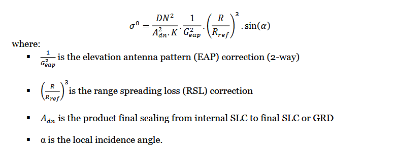
Radar cross-section is normalised in such a way (for historical reasons) that if Sigma0 = 1 = 0dB it corresponds to perfectly isotropic scattering, like what one would get for example from a metal sphere. If Sigma0 > 0dB more energy is directed back at the radar compared with the sphere, and if Sigma0 < 0dB more energy is reflected away.
Thanks again ABraun for your detailed reply and links which were informative. I now understand that the 32-bit format can just be a container for a variety of data types, and does not necessarily reflect on the data-type being contained.
Once S1 data are calibrated, although they end up in a 32-bit container, how many discrete values are there, e.g. is Sigma0 data in fact 8-bit with 256 values, 16-bit…?
To ABraun and mengdahl:
I’m sorry, I still don’t understand how >100% of radar signal can be reflected, even if multi-path. Is this a cumulative result? Sorry for being thick.
Thanks again for patient help.
almost infinite (probably limited by the number of pixels in total). They are stored as 32 bit float values.
One pixel can contain backscatter from many transmitted pulses because all kinds of signal overlay and scattering.
Thanks Abraun.
To help me understand, do you know what the actual calculation is that is made when calibrating the 16-bit GRD data so that it ends up with ‘almost infinite’ number of discrete values. I’m sorry. but there’s still something I’m not understanding…
On >100% backscatter . -got it! Thanks.
Source: https://sentinels.copernicus.eu/documents/247904/685163/S1-Radiometric-Calibration-V1.0.pdf
Source 2: https://sentinel.esa.int/web/sentinel/radiometric-calibration-of-level-1-products
May I ask why you are concerned about the number of discrete values in an image?
ABrauns explanation is not correct. As I tried to explain above what you call “> 100% backscatter” actually refers to “pixel is reflecting more energy back towards the radar than an isotropic (omnidirectional) scatterer would do”.
Here are some links to information on single-precision 32-bit float numbers in case you are interested:
Hmmm… my maths isn’t good enough to make sense of that, but I now understand why each pixel might be different, and why storing in 32 float is appropriate. So thanks for getting me over that hurdle.
The reason I’m getting hung up on the number of values, is that I’m trying to make sense of the resulting values from differencing two S1 images bracketing Hurricane Maria over Dominica. After calibrating, filtering and coregistering two images bracketing the event, the results are not intuitive, and so I’m trying to understand the data itself, but became confused with the DN values.
Many thanks again for all your help.
PS: Why does SNAP show the ‘raw’ GRD data as 32 bit INT for amplitude (32 bit float for intensity), when the ESA notes you copied above say 16-bit?
thank you for clarification. So volume scattering or double bounce does play a role here but energy received at a pixel is only emmitted from this location (and not neighboring scatterers)?
It is converted at the time of reading so that calculations can performed on it.
Largely so, but a full explanation gets into the technicalities of SAR focusing, antenna beam sidelobes etc. Perhaps @peter.meadows could give a more comprehensive response… 
I would already be thankful for some literature recommendation (regarding calibration) for non-engineers 
This is a great article about SAR in general:
http://www2.geog.ucl.ac.uk/~mdisney/teaching/PPRS/PPRS_7/esa_sar_tutorial.pdf
ps. don’t know why is has the word esa in the title…the article is published by DLR
What, like a corner reflector, for example?
DLR used to fly the E-SAR system. Looks like the ‘R’ dropped from the name.
ERS-1/2 were simpler systems than S-1 and their calibration is described here…for engineers I’m afraid 
Although ERS-1/2 SAR were simplier, their calibration was still quite involved especally while trying to understand the impact of the ADC - the document CAL01.pdf is from 1993! Although it seems the S1 calibration is more complicated, there is now a lot more information in the product annotation and documention to enable anyone, after some time, to perform calibration. After all there was not a tool like SNAP back in 1991.
Hi, Can someone still explain to me in simple terms how you get >100% of the emitted signal reflected back so that sigma >1.0?
Thanks
OK, got it. Thanks ABraun for helping me to understand.
All the best.
