Sentinel 1 GRD IW pixel resolution

The pixel “spacing” of the (high resolution) S1 images is mentioned as 10x10 m (range x azimuth)
The pixel “resolution” of the (high resolution) S1 images is mentioned as 20x22 m (range x azimuth)

however when l read the information directly from the files the values of the pixel size is demonstrated as :

px_size_x = 0.00020748…
px_size_y = 0.0001081327…

This means that in the case of S1 (unlike S2), pixels are “non-square”.
How one is supposed to interpret this difference?
Also is generalization of algorithms like co-registration (which I assume are based on square pixels) to non-square pixels erroneous?

I would appreciate any comment or material to read in this direction.
With regards,
Sina

Hi,

For the Single Look Complex data, the pixel size is not a square. The range resolution is higher than the azimuth resolution. This type of data is used for interferometry.

The spatial resolution you described in that post refers to Ground Range Detected (GRD) data. GRD data have a square pixel. Multilooking has been applied to this data so that the pixel size is square

1 Like

Thanks for this resolution. However this brings me to the next question:
why after reading this S1-GRD-IW image with SNAP tool and exporting it as a GeoTiff , the attached “geotransform” information contain such strange values?! what are these floating numbers stand for?

With regards,
Sina

Would you please to take a look at this might be answer your question,

Source : https://sedas.satapps.org/wp-content/uploads/2018/04/Sentinel-1-Product-Specification-2.9.pdf

Source : https://sentinel.esa.int/documents/247904/1877131/Sentinel-1-Product-Definition

1 Like

Unclear where you get this px_size_x and _y from, but they may be given as decimal degree. That could well translate to 10 m in both directions, depending where your image’ latitude is.

2 Likes

Thanks, these information seem interesting but for me as a sort of user sounds too (low-level). I am expecting to get such information directly from the metadata provided with the product measurement. Such that I can access them either through calling GDAL functions or access them within the (annotation) .xml files…

Maybe my explanation was not good. The problem that I have should not be very complicated.
As you may know unlike S2 products which are enhanced with GeoTransformation, S1 products do not provide such information. Lets take a look at the result of calling for this information using two random S1 and S2 tiles. When you call gdal’s gt=ds.GetGeoTransform():

the case of S1: gt = (0.0, 1.0, 0.0, 0.0, 0.0, 1.0)
the case of S2: gt = (499980.0, 10.0, 0.0, 1100040.0, 0.0, -10.0)

We know that the 6 provided values in each tuple are being interpreted as:
0 - Origin x coordinate
1 - Pixel width
2 - X pixel rotation (0 if image is north up)
3 - Origin y coordinate
4 - Y pixel rotation (0 if image is north up)
5 - Pixel Height (negative)

In the case of S2 one easily gets the width and height of the pixels from this metadata. (In case of different bands this pixel size value changes).
In the case of S1 though no information is provided. I have tested different hypothesis and came up with two Observations:

Observation 1):
If I use SNAP and select a spatial window from the S1 tile (manually providing Geocoordinates) and export it as a new image then the geotransform information is being added to the product which in my case is :
gt = (-51.390484599947186, 0.00020748114436486276, 0.0, 71.35720128316908, 0.0, -0.00010813274440124587)

here gt[0] and gt[3] correctly provide the coordinate (lat/long) of the north-western pixel Img(0,0).
gt[1] and gt[5] are supposed to present the pixel width/height.

There are two problems here however:
First) These values are not the same as you can see.
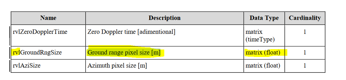
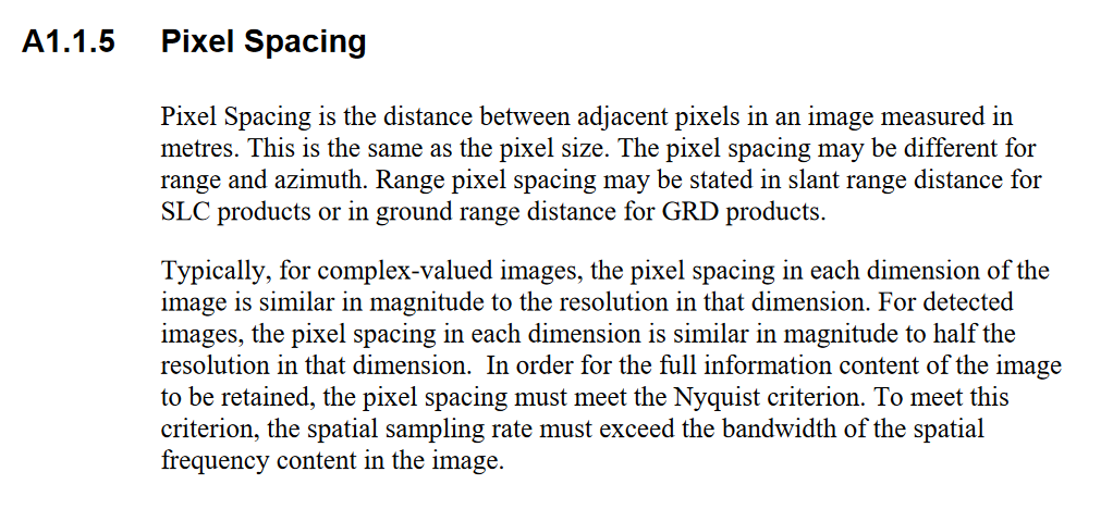
Second) I can not relate these values to 10x10 size that is mentioned in Sentinel-1 manual. why these values are such small fractions?

Observation 2):

I noticed that within the metadata of each S1 tile there is a collection of ground control point GCPs which is possible to access either by reading annotation .xml files or simply by calling ds.GetGCPs() function of GDAL. Within these GCPs one can find the coordination of 4 pixels representing the four corners of a tile. therefore by having these coordinates and the number of pixels in each dimention we can calculate approximately (in a linear sense) the width and height of each pixel. When I did this the result of calculation is again far from the expected value 10.

I would appreciate your comments on these observations.
With regards,
Sina

Decimal degrees indeed. Since you’re at -51.4 lattitude, x-spacing is indeed about 2x y-spacing. Check conversion from dd to metric. SNAP probably picks up some metadata with approximate coordinate information. Nothing magic about this.

1 Like

You anyway should not use S-1 GRD without terrain correcting them first, unless you are working on salt flats or water surfaces (in which case ellipdoid correction would be enough). Using GRD:s “as is” could work for browsing purposes only if you are not interested in exact pixel locations anyway.

1 Like

Thanks for this comment,
Sorry if my question seems obvious !
I understand that for converting the coordinates of 1 single point we can switch between three presentations, namely :

Decimal Degrees (DD)
Degrees decimal minuets (DM)
Degrees minuets seconds (DMS)

by simply multiplying the fractional parts by 60 . Considering the longitude of my pixel
Long(0,0) = -51.390484599947186 (DD)
it means :
0.390484599947186 x 60 ~ 23.429075
Therefore:
-51 ^ 23.4290 (DM)
and again:
0.4290 x 60 ~ 25.74
Therefore:
-51 ^ 23 ’ 26 (DSM)
This conversion I understand, however I can not figure out the conversion procedure behind the “pixel size” (gt[1]) value. Under which sort of conversion I am supposed to come from a number near 10 to a fraction near 0.000207… ?

Thank you very much.
You are right and in my case (motion estimation) I definitely need an accurate co-registration which by itself means I need to have as accurate as possible geo-location of the pixels and here I assume your suggestion for applying “terrain correction” is needed to be considered before the co-registration. This will be my next step. At this time I want to check the results of my workflow including co-registration and offset tracking on S1 data as-it-is. and in the next phase I will compare the results of the procedure considering the train-corrected images. However as I am currently considering a relatively flat area (near sea) for measuring Ice movement, I hope that I get some acceptable offset tracking result even without applying terrain correction.

I’m sure the traking works best in GRD geometry - you will need to terrain correct the result.

By the way when you say GRD “geometry” I assume that you want to distinguish between SAR geometry and this GRD geometry. Am I right? From the sentinel manual I know that “Ground range coordinates are the slant range coordinates projected onto the ellipsoid of the Earth”. But isn’t it that the S1-IW-GRD products are “already” transformed into this GRD geometry? I am particularly asking this based on the content of this page: S1-GRD

Yes the GRD-geometry is in ground-range and not the original slant-range SAR-geometry. If you use GRD:s for offset tracking it’s best not to reproject them again in any way.

1 Like

I think I solved this issue. For those that might later raise the same question and are not familiar to Geospatial calculations:

The calculation of distance in metric using Longitude/Latitude information of two points is done using Haversine (great circle distance) function. After having calculated this distance (in meters or kilometers) one can divide it by the number of pixels( across columns/rows) and respectively come up with the pixel width/height. When I did that using sintinel-1 GRD IW, ground control points of 4 corners of a tile, the pixel size valuse are close enough to the expected value of 10.