SLC to GRD workflow. Different steps

Hello,
I am working on the sentinel 1 data, IW, Dual polarisation (VV+VH).
I have worked with:

  1. GRD data directly https://scihub.copernicus.eu/dhus/#/home.

IW, DV ((VV+VH):
Amplitude_VV, Amplitude_VH
Intensity_VV, Intensity_VH.

  1. SLC data ( https://scihub.copernicus.eu/dhus/#/home).

IW, DV ((VV+VH):
i_IW1_VV, i_IW2_VV, i_IW3_VV, i_IW1_VH, i_IW2_VH and i_IW3_VH
q_IW1_VV, q_IW2_VV, q_IW3_VV, q_IW1_VH, q_IW2_VH and q_IW3_VH
Intensity_IW1_VV, Intensity_IW2_VV, Intensity_IW3_VV, Intensity_IW1_VH, Intensity_IW2_VH, Intensity_IW3_VH.

I have tried to process SLC data to obtain GRD compare with the results obatined in 1) but I don not have had the same result in 2)

I would like to compare 1) and 2) in order to be sure that I get same (or similar) GRD product.
I have proceeded using S-1 SLC to GRD but GRD obtained is still separated into inicial three sub-swaths per polarisation.

Other documents/tutorials speak about different workflows as: Tools/GraphBuilder/Graphs/Radar/InSAR Graphs.

So, I need to obtained SLC as: Amplitude_VV, Amplitude_VH, Intensity_VV and Intensity_VH.

Have you ever used the SLC to GRD algorithm in snap? Am I doing something wrong?

Thanks,

Juanjo.
You still need to merge the subswatths. In any case, that graph will generate a ā€œGRD-likeā€ product, not a replica of an actual GRD.

not sure if I understood your point, but the ā€œS-1 SLC to GRD but GRDā€ operator applies Radiometric calibration which converts Amplitude/Intensity into Sigma0. You can create your own workflow using the graph builder and skip this step.

But may I ask why you want to convert SLC to GRD products at all when these can be directly downloaded?

Thanks @mengdahl, It will be merged.

Yes, I know that ā€œGRD-likeā€ product is not a replica of an actual GRD but I need to compare them in order to understand what GRD from ESA I am downloading.
Documentation and ESA tutorial describes it but when I explored GRD there is no coincicence, georeferenced for example. Documentation speaks about it is but it is not.

Juanjo

I need to compare them in order to understand what GRD from ESA I am downloading.

Juanjo

sorry, I donā€™t get this point. What is your concern about the GRD data provided by ESA?

You can safely assume the official GRD is of higher calibration accuracy for example. I would be surprised if the official GRD documentation (see S-1 product definition) is incorrect - can you be more specific?

Sureā€¦
For example:

Level-1 Ground Range Detected (GRD) products consist of focused SAR data that has been detected, multi-looked and projected to ground range using the Earth ellipsoid model WGS84. (https://sentinel.esa.int/web/sentinel/user-guides/sentinel-1-sar/product-types-processing-levels/level-1)

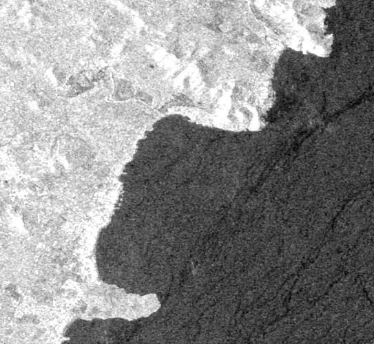
GRD downloaded:


Inverted

GRD after GRD workflow:

Subset (georeferenced)

Maybe I am wrong or I did not undertand the info correctly, I do not know.

Juanjo

GRD Workflow:

image

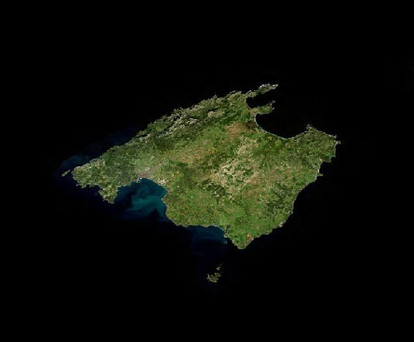
Area (reality)

My concern are:

  • I would like to compare GRD offered by ESA and GRD obtained from SLC doing my self. We need to decide if we use SLC or GRD product on our project.

  • We have get GRD product perfoming Google Earth Engine. If we compare GRD from ESA and GRD from Google Earth Engine are a little bit different. It is necessary explore SLC to GRD workflow.

Thanks,
Juanjo

The S1 GRD data you find in GEE is described here and also here.
You should note that the data available there has already been pre-processed using SNAP+s1tbx, so for sure it will be different than the one from the hub!

I think you need to explain your problem better so that the expert users in this community can try to help - as is your message is quite confusing, even to me that I am not an expert.

2 Likes

Thanks Cristino, very useful.

I will check it. First af all, I need to understand what googe earth engine GRD is offered and after I will try to understad hub offers and finally process SLC to GRD into SNAP and compare all of them.

Best regards,

Juanjo

Hi @cristianoLopes,

I have checked your post and I need some clarityā€¦

First link (https://developers.google.com/earth-engine/datasets/catalog/COPERNICUS_S1_GRD) shows how each scene has been pre-processed using Sentinel-1 toolbox:

  1. Thermal noise removal
  2. Radiometric calibration
  3. Terrain correction using SRTM 30 or ASTER DEM for areas greater than 60 degrees latitude, where SRTM is not available. The final terrain-corrected values are converted to decibels via log scaling (10*log10(x)).

ItĀ“s ok, I understand. ItĀ“s similar to my workflow GRD_Hub to GRD.
However, the article linked (https://developers.google.com/earth-engine/guides/sentinel1) to those steps shows:

  1. Apply orbit file; restituted orbit file.
  2. GRD border noise removal.
  3. Thermal noise removal.
  4. Radiometric calibration.
  5. Terrain correction; orthorectification); using SRTM 30 meter DEM or the ASTER DEM for high latitudes (greater than 60Ā° or less than -60Ā°).

Both workflows are clear but I need to know which one is followed to obtain GRD.

Thanks in advance,

Juanjo V.

Why not ask to the GEE support (follow from here)?
My reply was an attempt to get you to search for information yourself - most of it is public.

This is a SNAP forum, a place to for obtaining community help for a specific ESA software - not Googleā€¦ this doesnā€™t exclude that someone in the community is able to help you but just donā€™t expect this upfront.
Please also note that ESA is not responsible for how data is managed outside the official the official distribution channels - i.e. in GEE, AWS, etc.

Sure, sorry for that. I am asking to GGE too.

I was explaining , as a introduction, what I am done with GGE in order to compare with ESA GRD product.

Focused on GRD ESA, Sentinel -1 on -line documentation (https://sentinels.copernicus.eu/web/sentinel/user-guides/sentinel-1-sar/product-types-processing-levels/level-1) speak about GRD corrected (using the terrain height)ā€¦etc:
ā€˜Level-1 Ground Range Detected (GRD) products consist of focused SAR data that has been detected, multi-looked and projected to ground range using the Earth ellipsoid model WGS84. The ellipsoid projection of the GRD products is corrected using the terrain height specified in the product general annotation. The terrain height used varies in azimuth but is constant in range (but can be different for each IW/EW sub-swath).ā€™

but in order to get GRD georeferenced you need to pre-process the scene because doen not is showed (SNAP) georeferenced, this is my confusion.

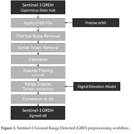
Several authors explain this processing as:
image

At the begining, I thought GRD ESA product was as Sentinel -1 on -line documentation explain,

Thanks,

Juanjo

I think we are mixing two different things.

The explanation you quoted is how geocoding is stored in GRD products in general (multi-looked Amplitude/Intensity, as you can download them in the Copernicus data hub) while the workflow you show in the figure is the conversion of these GRD products into radiometrically calibrated and terrain-corrected Sigma0 values. As you say, the latter is not provided for download.
Buit I agree that the documentation how exactly this is done in the Google Earth Engine is not very detailed.

1 Like

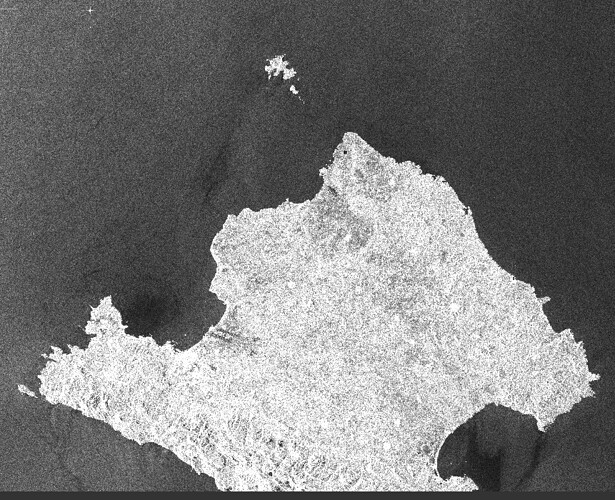
I agree @ABraun about how is geocoded is stored in GRD products and workflow explains how to get sigma0 values. Anyway, when you download GRD product from Copernicus data hub scene is inverted and not georeferenced.

ā€˜I think we are mixing two different things.ā€™ This is I am tryinng to solveā€¦

Juanjo

it is inverted because of the ascending orbit, but it still contains geocoding information which allows to project it accordingly. This product level gives the user the freedom to select the way of pre-proessing and all its parameters (resampling, coordinate reference system etc.), but conains all necessary metadata to do so.

2 Likes

Additonal: Terrain correction moves image pixels to their exact location based on an underlying DEM. This is more precise than the geolocation information which is stored inside a GRD product. At the same time, the data is projected into a coordinate reference system. In most cases, this means that north is at the top afterwards and the image is rotated accordingly.

Please check the explanations in this tutorial: SAR Basics with the Sentinel-1 Toolbox

Similar, but with additional radiometric normalization: How to radiometrically terrain correct Sentinel-1 data

1 Like