We’ve been working on doing the mapping of water inside a salt lake using sentinel-1 images (We take the GRD data, and then we do some preprocessing like sigma calibration, speckle filtering, terrain calibration…), and We’ve been doing very well.
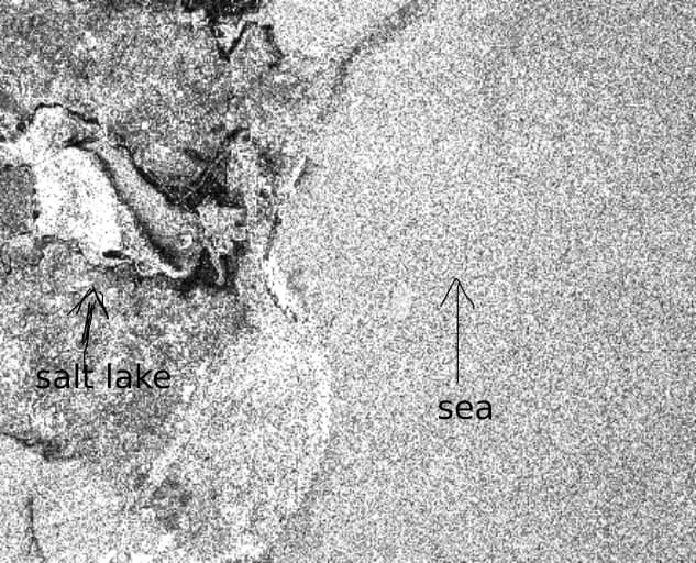
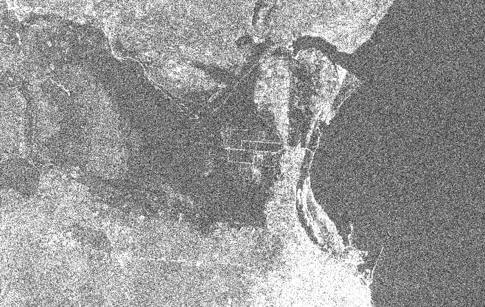
However, This month we observed some strange patterns in the data; The backscattering became very high; either in the lake, or in the sea; Both of them; the lake and the sea became very bright (like you see in the following image)
So, Now we are not able to detect exactly the water inside the lake.
Do you have any idea of what could be a reason for this? and can we correct it?
because as I know; if it’s bright, then there’s something that caused roughness. Right? Or is it an anomaly?
Note: The strange pattern occured in June, the 9th, and the usual one is in June 14th. The next figure represents the weather in these two days:
To be able to help you, could you please give me some informations :
The strange image does not seem to have the same level of process than the correct one, could you confirm this to me ?
As your two data are only separated by 5 days, I guess that they are not obtained using acquisitions in the same path. Could you precise the satellite path on your image ?
Could you give me the times of acquisitions, or to allow me to do the same study the product names ?
Did you use the same colorbar min/max for the two images ?
My first idea would be that it is due to Bragg effect due to wind, but to confirm that we need to do some further studies
The backscattering of the sea surface depends on the polarisation, the wind speed and direction and the incidence angle
For a given wind direction toward the sensor, the higher the wind, the higher the backscattering.
You can find good explanation of this here.
This is caused by the wind creating gravity waves at the surface. The pattern of those surface wave creates Bragg scattering when observed by the radar imager.
In your two examples:
The medium wind speed over ocean is around 6m/s
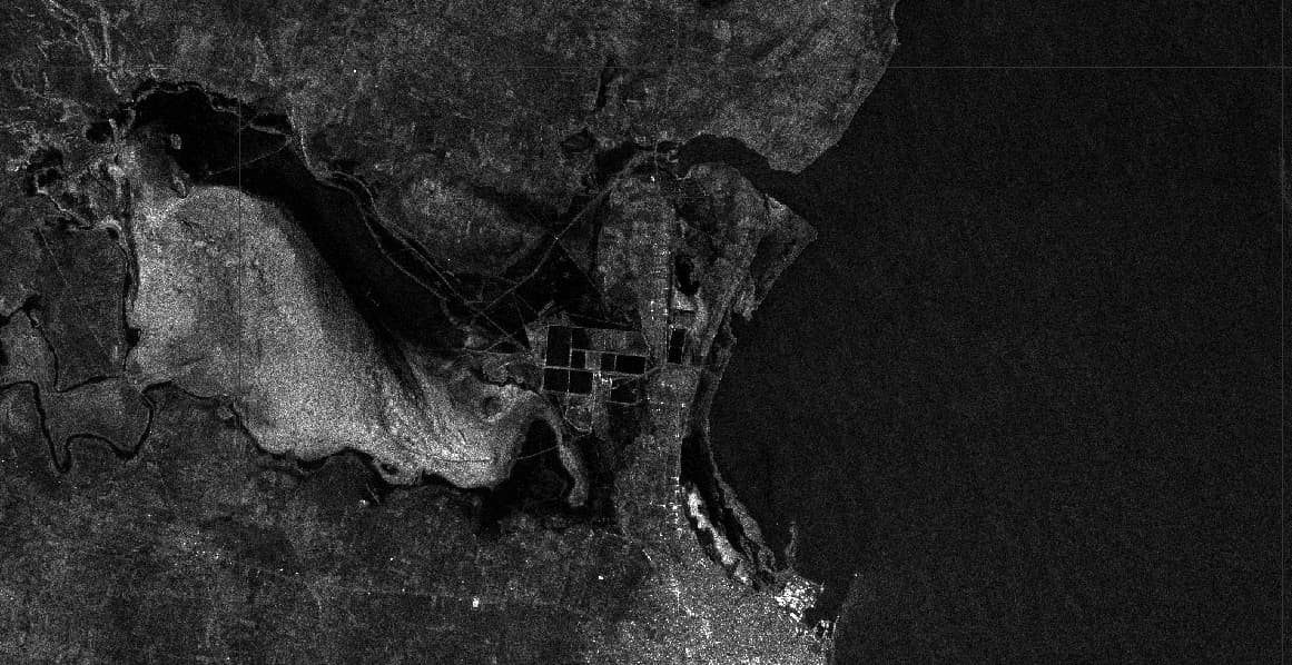
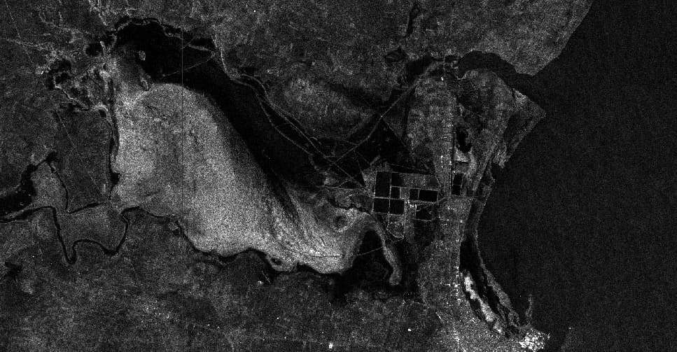
on the 9th of June, the wind speed is around 3 m/s which is low wind → low backscattering
on the 14th of June, the wind speed is around 10 m/s which is high wind (not extreme, but high wind) → high backscattering
The backscattering of the sea surface is much lower in cross polarisation (VH or HV) compared to co polarisation (VV or HH). You should be able to see more clearly the limits of the lakes on cross polarisation images, even in high wind conditions.
Then @NourSoltani , can you please provide the names of the two images ?
This can be due as well to different incidence angles on the two images due to acquisitions on different tracks / relative orbits.
The higher the incidence angle, the lower the backscattering (all other parameters being unchanged).
Thank you for your response.
Well I apologize, There are some differences in the two figures that I’ve already provided… I shared, by mistake, a the VV polarisation data for one, and the VH for the other.
Here’s the VV, and VH for both:
Thank you for responding:
Yes! of course:
2023-06-09 (Unusual/ High backscattering/ Water is not clear inside the water lake): S1A_IW_GRDH_1SDV_20230609T171152_20230609T171221_048912_05E1C6_E48D
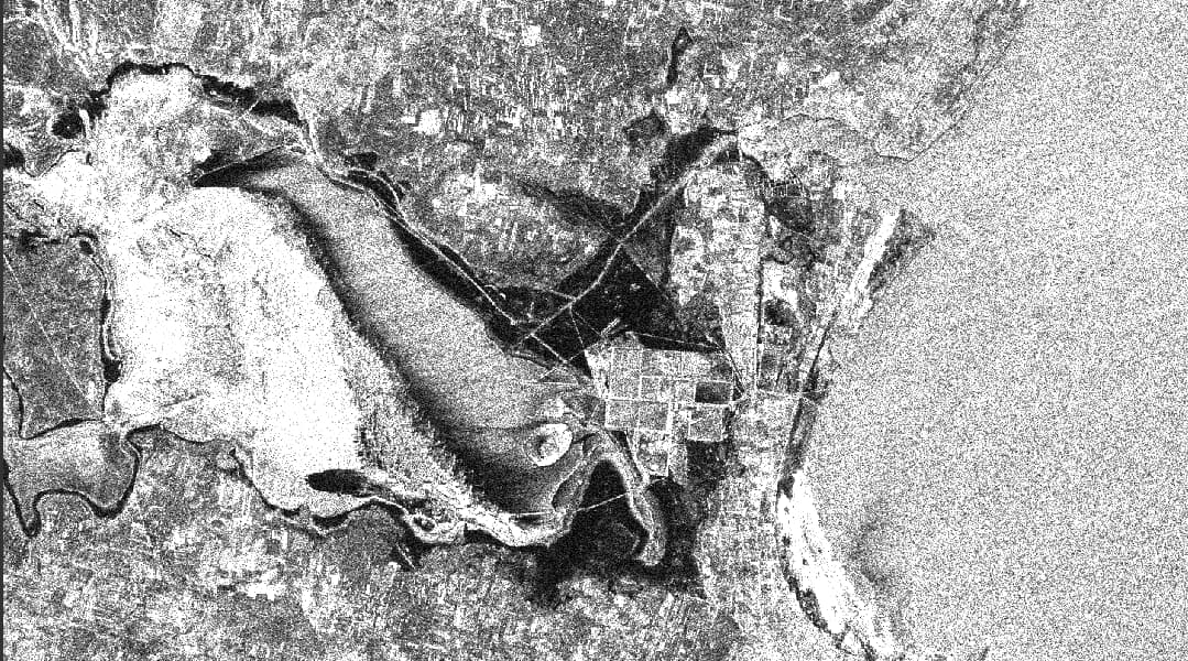
2023-06-14 (Usual/Low backscattering/ Water is clear inside the water lake):
S1A_IW_GRDH_1SDV_20230614T172003_20230614T172028_048985_05E406_1B97
The initial colorbar depends of your images values. As they are not the same in the two acquisitions, and for the two polarisations, they are different for every images you have shown us. Here is for example two images for the first date
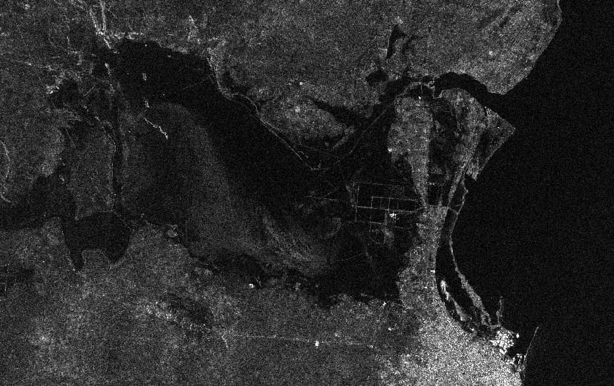
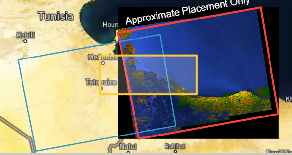
Secondly the answer to your problem is I think due to the different path. If you look at the following image obtained on ASF for your 2 acquisitions
You can see that for the left one (14/06) your lake is at the end of the swath (around 43°), whereas for the right one (09/06) he is at the beginning of your swath (around 30°). Therefore you don’t “physically look” at the same thing, as the incident angle is different. It is therefore not surprising to obtain different values for a water area in C-Band, even without important wind conditions.
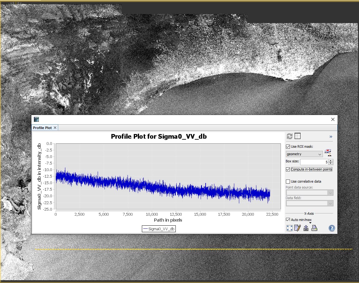
Here is an exemple of the impact of the incidence angle over an “homogenous” area of water. You can see that the Sigma0_VV decrease when the incidence angle increase, the profil being the Sigma0_VV in dB over the yellow line in the sea.
To be able to confirm this theory, you have to use or data acquired with Path 15 and Frame 103, or data acquired with Path 88 and Frame 103. You can’t compare data acquired with different paths, as you won’t “see” your target the same way for the different paths, unless you look at an isotropic target as a sphere.
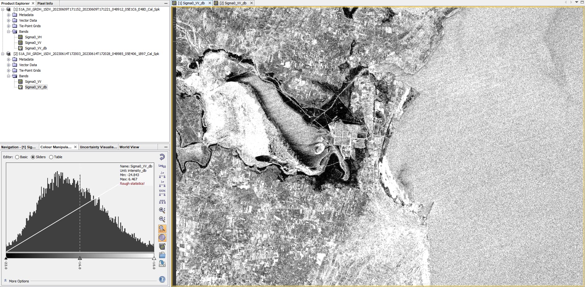
Finally I think that your result here
for VV is wrong, as it is really really different of what I obtained and of your other results. What are you displaying ?
Quick question, you talked here
about terrain calibration and I thought that you were talking about Terrain-Correction, but I deduced from your images that you did not Terrain-Corrected your data. What did you mean with this “terrain calibration” ?