Toolbox version and operating system: tried both:
2.0 (according to version.txt but 'About SNAP in Mac toolbar says version 1.0). Mac Yosemite.
2.0 (2.0-beta-08; linux)
amount of RAM: 16GB
relevant satellite products by giving the full name of the product: S1A_IW_GRDH_1SDV_20150517T152239_20150517T152304_005963_007AEC_A4B9
exact processing steps needed to recreate the issue: display intensity in SNAP as it is; or Calibrate -> sigma0 display
I found low level signals of VH or VV show alongtrack stripes on either side of each ScanSAR images of one GRD file. The stripes are visible in low sigma0 for example when VH plotted with -25 to -15 dB, or VV is shown in -20 to -10 dB range (see the attached image below).
Is this because noise-removal was not applied to GRD? Combination of noise profile and antenna gain profile with respect to the range direction can cause such stripes at the edges. I searched existing QAs in this forum. Some say that noise was removed; others say noise was not removed. To the above intensity scene, I applied Radar->Radiometric->S1 Thermal Noise Removal. Comparing Calibrated sigma0 with/without the noise removal, however, there is no difference (the two sigma0s are nearly the same in dB). Noise removal might be the reason, but noise removal by SNAP 2.0 does not seem to have any effect.
Also wonder if any error in the antenna pattern correction can cause such stripes. Such error may come from errors in attitude knowledge.
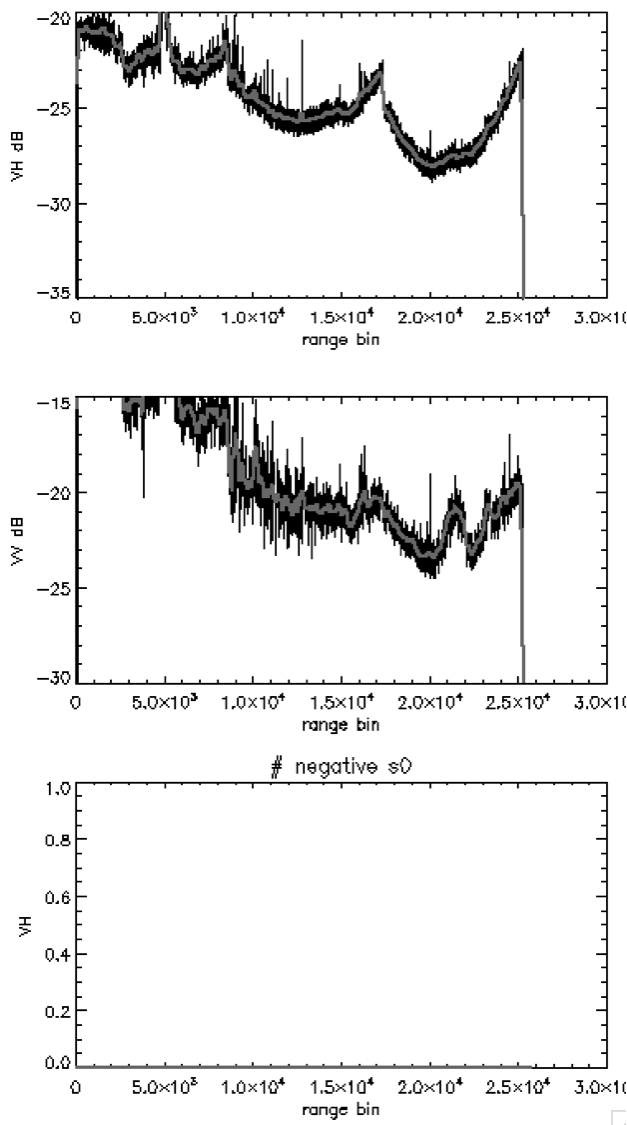
The striping patterns appear in many other IW GRD scenes. Below is the output of ‘Calibrate’ for
S1A_IW_GRDH_1SDV_20150517T152239_20150517T152304_005963_007AEC_A4B9. Top is VH, bottom is VV.
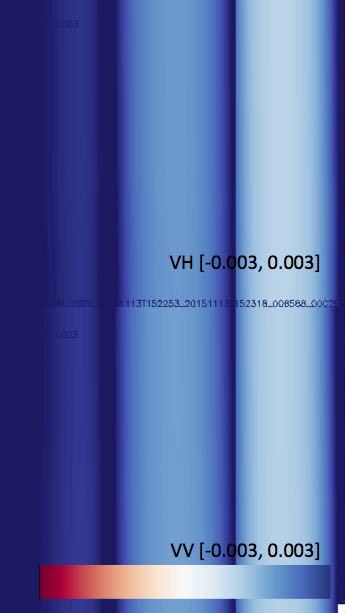
Strange is that, as I wrote in the original post, the output of noise removal is identical to the original GRD. I applied ‘Radiometric’->S1 Thermal Noise Removal’; then applied ‘Calibrate’ to both of original GRD and noise-sub GRD. The difference of the two is shown below. The flat grey is at grey level 122 everywhere, which corresponds to 0 dB difference…
I seem to remember that the noise LUT in the calibration files were certified for use only recently. The values in your image seem too low for the de-noise operation to make much difference. I’d advise you to try more recent images of the same area.
Thanks. Following your suggestion, the following granule of Nov 13, 2015, over Saudi Arabia was tried: S1A_IW_GRDH_1SDV_20151113T152253_20151113T152318_008588_00C2E9_1746
The striping is still there after noise removal (but unlike the May 2015 scene, noise removal does something though not properly!).
The plot below shows the size of noise subtraction (in power unit). Qualitatively it resembles the theoretical noise profile that is shown in ‘presentation359.pdf’ referred in css’s post above. This suggests that the noise subtraction is doing is job but not perfectly. Some questions… Why not perfect? Is it because the noise LUT is static but the actual noise floor is dynamic? Why is the LUT the same between VH and VV?
The denoising vectors are only working since July 2015 (announced at IGARSS).
Thus for data processed before that date the denoising is not working fine.
For data processed after the denoising should work. However, if the data is not really at noise floor the denoising won’t be fully efficient and a residual will still be present. This is I believe what is happenign with this data over the desert.
For example, over ocean under very low wind speed condition, we are measuring sigma nought down to below -28dB at mid IW2 or -31dB for mid IW3. I can see from some plots above that it is hardly hitting -26dB (IW2), -28dB(IW3) in this desert.
If the denoising is applied on this data the result will not be perfect as the is close but not yet at noise floor. A residue is then expected.
Answering another question: Just to be sure to understand but if we apply noise reduction we should reduce striping effects?
Denoising is often only needed for the cross-pol (over land). The noise floor pattern (see for example http://seom.esa.int/fringe2015/files/presentation359.pdf page 5) creates sub-swath jumps and this is visible between EW1/2 but it is true for all other beams. The denoising should help in removing as the ‘ultimate’
goal is to set pixel Digital Numbers (DN) down to 0. Indeed, if data is at noise floor there is no signal coming in the antenna. The denoising should bring down the DN close to zero and thus reduce the sub-swath noise pattern transition.
Indeed, I have tried to process more recent data (november) and even if the data itself seems to be less affected by the sub swath variation, the thermal nois removal tools is working well.
I will try on other data in same area (Guiana Shield) but it’s a very good news !
In addition but off topic I will create another post to give our very positive feedback on Snap and Sentinel-1 in the context of forest monitoring in our Guiana Shield project.
I am communicating directly with Nuno and posting some of the communication here for the sake of everyone else.
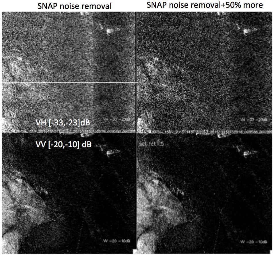
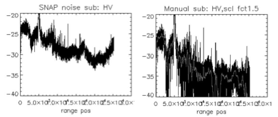
Yes the scene (S1A_IW_GRDH_1SDV_20151113T152253_20151113T152318_008588_00C2E9_1746) is brighter than the noise level. If the noise removal is perfect, we should see the geophysical sigma0. The fact that we still see the stripes, the noise removal is not perfect. When I increase the amount of noise removal by 50%, the stripes are largely gone (right column below).