I don’t know how I can it explain it any better than above.
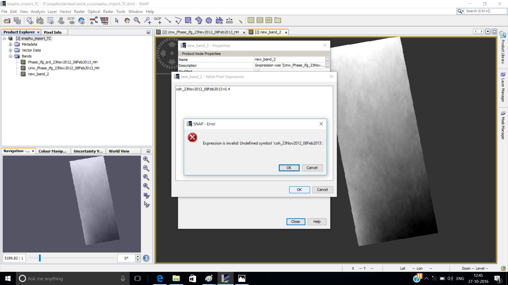
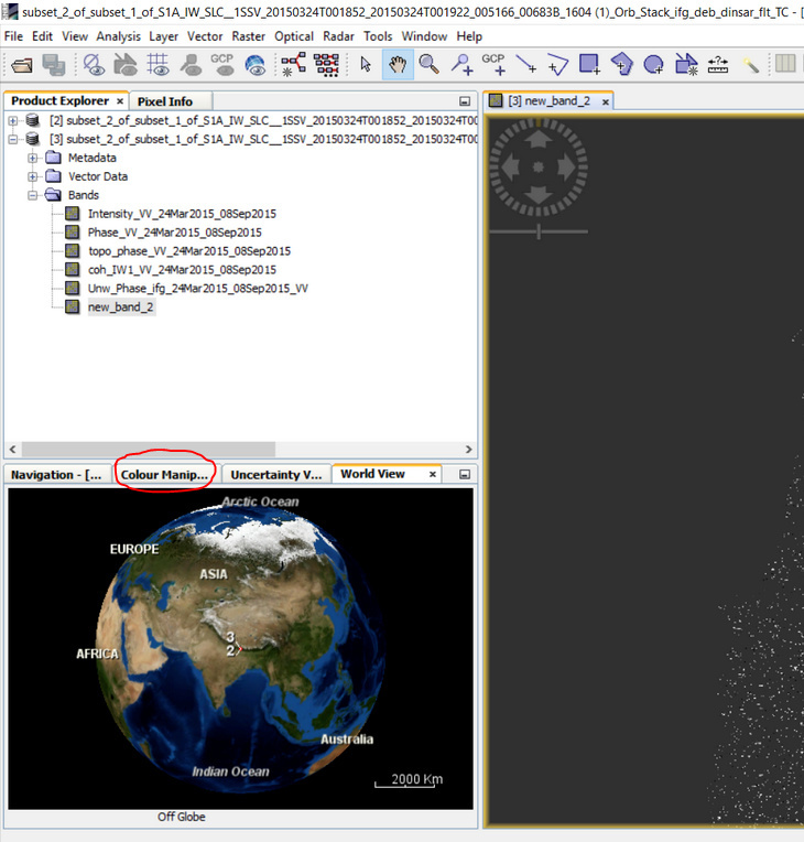
You don’t get information about subsidence from the coherence layer. You only use it as a spatial indicator of quality of your phase information. Therefore, you don’t apply the masking of low coherence on the coherence but on the unwrapped phase information (band 3 in your case). Then you will have the areas where your information is reliable. You can also lower the threshold to 0.4 in order to get larger valid areas.
Sorry, but it seems that you follow a recipe while you aren’t aware of the meaning of the single steps. InSAR is not trivial, undoubtedly. But one should be clear about what is done and why before processing.
and again:
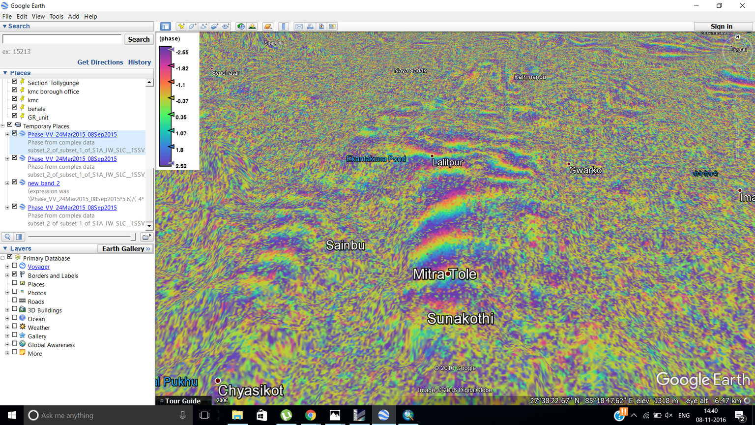
However, there’s a strong ramp in your image wich distorts the result massively. I don’t think you did anything wrong so far but maybe there’s too much time between your images.
I’d like to say what is mentioned by ABraun in most digestible words, In InSAR Processing chain there are a lot of steps, SNAP concise most of this steps in general and short by including the other within the major steps, the other thing I’d say is each process step has many parameters, in any processing case we try to play with this parameters increase or decrease according for example to study area the per.Basline and TemBasline, Atmoshperic effects and so on, So try to play with those parameters by taking in your account a short TemBaseline for instance in Sentinel-1B only six days, that would clarify many matters for you.
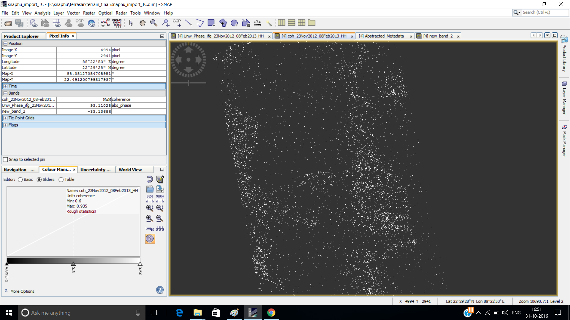
ABraun till now i am ok with the steps… i did the band calculation, eliminating the pixels that have low coherence , and select a point where i assuming no change and its value shows in pixel information tab is 20.48 …
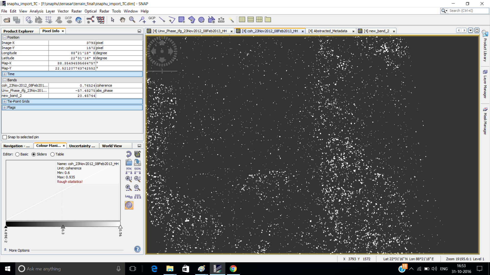
one more thing is that… when i move my cursor both for unwrapped phase and coherence image the pixel information value is gradually increasing in positive figure upward and in negative figure downward respectively,
the result is your subsidence in cm. According to your histogram its mostly positive. But given that you proceeded correctly this is how you technically derive it.
As already stated
You could try eliminating the ramp with a modeled surface but at this point you’re theoretically through all steps.
"Select a point where you assume no change and read the value. Let’s say its 45 cm
Subtract 45 from your imagein order to have zero values at those areas with no change. The remaining variation should be due to subsidence between two overpasses"
if your raster is 20.48 where it should be actually 0 just subtract 20.48 from your raster with the band maths operator to kind of level it to the ground. The remaining variation is the subsidence.
one morething … i am eliminating the pixel that have coherence value below 0.5 …now how am i choose these specific pixel in my subsidence image(band math image) …
some value in subsidence image (band math image) showing positive value and some are negative ones… is positive subsidence i.e the positive value means subsidence or the negative value
yes i did this step …
after that i do band math on unwrapped phase and valid pixel expression on coherence image… now i want only these pixel that have high coherence value in my unwrapped phase image.
this is my subsidence image overlaying with google earth… the legend shows the value of subsidence…is there any way in the software least i zone out the areas which are prone to change…