it seems that your phase information is not unwrapped yet. Unfortunately, it also seems that you don’t know what you are doing so please learn the basics first. I am really sorry but I can’t help you getting results like this.
The information on the way to mask out the area of low coherence and subtracting the value obtained at the point of no displacement from all pixel is really helpful. Thank for that.
I was wondering if I can follow the same procedure for obtaining the displacement of the glaciers. Especially, step 3 and 4??
Thank you. I am aware of offset tracking process. But I am also aware that the result of DInSAR is very accurate than offset tracking. In addition, with combined Sentinel-1 A & B, I have image pair of 6 days temporal baseline. I also found image pair with good coherence. I can see fringes suggesting the displacement. I am only unsure about the process after the “Phase to displacement” step. Because I see some values in the rock which should not be the case.
I applied the topographic phase removal then i can clearly see the fringes only on the glaciers. How do I make sure whether the fringes are due to atmosheric artifacts? I would really appreciate any help on this matter.
I also read that atmospheric artifacts are removed when correcting the orbit. Or is it not?
Orbit correction removes most of the orbital fringes (fringes resulting from errors in the flat earth correction). Atmospheric fringes still remain, but they do not follow glaciers so you should be able to tell the difference between them.
can you explain briefly the last step … i identified the stable pixel …now i want to subtract the value of it with the remaining pixels to get the subsidence results … please explain the last step briefly
your post is very interesting. By the way I cann’t get what do you mean with “apply orbit file before your co-registration”. Could you explain me better this step?
Thank you so much!
The orbit state vectors provided in the metadata of a SAR product are generally not accurate and can be refined with the precise orbit files which are available days-to-weeks after the generation of the product.
The orbit file provides accurate satellite position and velocity information. Based on this information, the
orbit state vectors in the abstract metadata of the product are updated.
Applying orbit files in SNAP:
Menu > Radar > Apply Orbit file
You mentioned about the data displacement extraction using DINSAR and high coherence region was reliable. However here I have a question about when high coherence region be selected?
there are two options here.
(1) select unwrapped phase with high coherence, then filter it and use SNAPHU to unwrap it.
(2) select unwrapped phase without considering coherence, then filter it, use SNAPHU to unwrap it and select displacement with only high coherence.
Do you think we should follow (1) or (2) when conducting DINSAR processing?
Thanks for all your instruction and response in this forum.
you can unwrap the whole image without considering the coherence at first, but you should later consider it when you interpret your result, e.g. masking out low coherence areas.
Thanks for the reply. I will try both.
Processing the whole image is time consuming. However only unwrapping phase from high coherence may cause some problem as the phase may be spatially unconnected. That is my concern.
Hi,
I’m trying to create a subsidence map using the steps mentioned above.
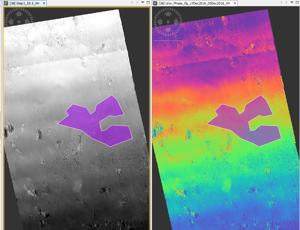
It looks like that I have a problem. My unwphase images (always) have values which decrease from one side if an image to another. As a result Step1 image [(Unw_Phase * wavelength in mm) / (-4 * PI * cos(rad(incident_angle)))] has the same pattern of its values too. Values here fall from 65 on the north to - 20 on the south of image. I can’t find where my mistake or how to fix it.
My processing steps.
Split
Orbit file
Deburst
Coregistration
Ifg creation
Topophase removal
Goldstein filter)
Unwrap
What ABraun mentioned in the post Sep. 8, 2016.
I tried all the precessing steps possible: with and without topo, range and azimuth filters, all the options of Unw Export, etc. Despite that I always receive these “angled” unw.phases.
Please recommend me something. Thanks!
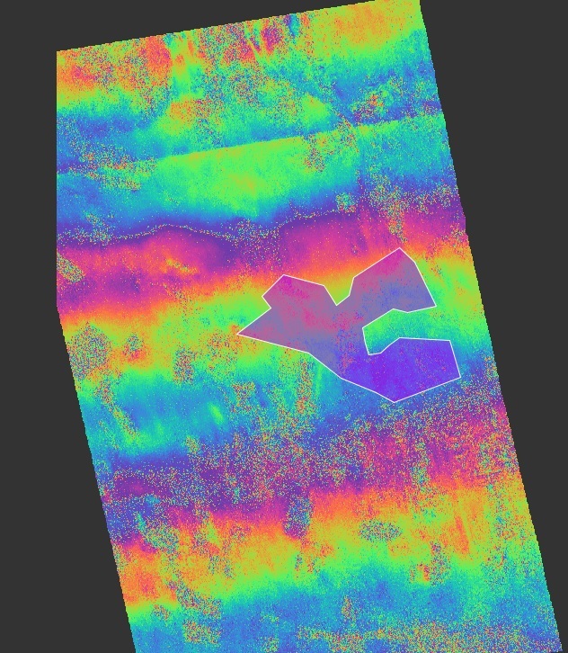
This is my phase.
Here I have a baseline of 24m since I used 2 closest passes of the same sattelite. But in another case, I have a baseline of 80 m (2 satellites used) and unw looks the same. I started to think about SNAPHU, maybe is it possible that it works wrong?