The impact of topography on your phase is too low. Try another image pair with a higher baseline:
1 Like
Hi ABraun,
Actually I could not make Snaphu Export working when using the phase after masking with coherence threshold.
I used the coherence coefficient (threshold=0.50) to create a mask and used this mask to extract related phase (wrapped). A new phase band was generated. I gave this new phase band a different name (compared with the original phase name) and added it to the original data file. In this way, Snaphu Export worked and after unwrapping process, I noticed that the new phase band I generated was not used since no data gap was found in the unwrapped phase.
Then I tried another method. Deleted the original phase and gave the new phase band the same name as the original one. However Snaphu Export did not work and the reminder is “Wrapped phase band required”.
Snaphu Export did not find the wrapped phase band which was not because of the file name of wrapped phase band. Maybe because of some other information in the original data file. However I just created the new phase band with Band Maths, I did not think I changed much head information of phase band. Maybe the developer of SNAP can help to explain this.
Best,
Xianwei
Masking and unwrapping was reported to have issues several times. Try unwrapping the original phase and mask out low coherence areas at a last step.
Would you like to tell me please, what is a vertical resolution of a subsidence map? Does it equal to a wavelength?
It depends on the level of phase-noise (coherence) and can be a small fraction of the wavelength. Please note that the error-sources (atmosphere and ionosphere) are much larger than this.
mengdahl, thank you for your answer. Could you please suggest me something to read about it. Maybe some equations or something…
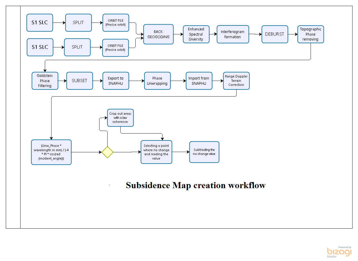
I’ve been managed to create a nice subsidence map. Thanks to ABraun and his formulas.
These are the processing steps I’ve taken. On a finish of the process, I created a decision point: you may not exclude the low coherence points for having a map without empty places If you can accept possible mistakes caused by insufficient coherence.
These are the processing steps I’ve taken. On a finish of the process, I created a decision point: you may not exclude the low coherence points for having a map without empty places If you can accept possible mistakes caused by insufficient coherence.
4 Likes
Pardon me, Tomcater, but isn’t the RD Terrain Correction supposed to be the last and final step of the processing chain? Can you explain your reasoning why you carried out the band math phase to displacement operation and pixel subtraction after geometric correction?
Thank you!
Hello ABraun,
I myself am also struggling with eliminating a phase ramp in my study area that occurred during unwrapping. This post of your is quite interesting, though I was unable to find any information as to what it might mean. By a “modeled surface” do you mean a more accurate DEM to be used during topographic phase removal or are you referring to a different operation altogether? Any information on this (links to papers included) would be greatly appreciated.
Thank you!
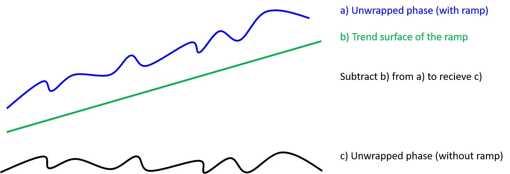
what I meant was to somehow create a raster that shows the overall trend of your ramp. If you can get that, for example by selecting and interpolating points at regularly distributed points you can then subtract it from your unwrapped phase.
My colleague does this because his TanDEM-X data maybe lack of precise orbit state vectors and this creates a ramp that superimposes his interferogram. With basic GIS steps (creating points between fringes, reading out phase values, interpolating points to get a surface of the ramp) he managed to reduce the ramp to a acceptable degree. But it’s just a work-around.
I quickly made a image to illustrate it:
Hi, Momut1
I do it because Local Incidence band is created by Range-Doppler TC. Before it, this band does not exist.
I have a suspicion that Back-Geocoding + ESD without any Subsets provide minimum ramp possible.
Very interesting. Can you perhaps share your colleague’s name and/or results or perhaps a paper he might of written/collaborated on documenting the process? I will try his method, but having a paper to reference is always helpful. As far as I understand from your post he does this when no precise orbits are available for his images. I am curious then if the process works well in the case of applied precise orbits.
By “local incidence band” you mean the incidence angle raster located in the tie-point grids folder of the product?
Vis a vis:
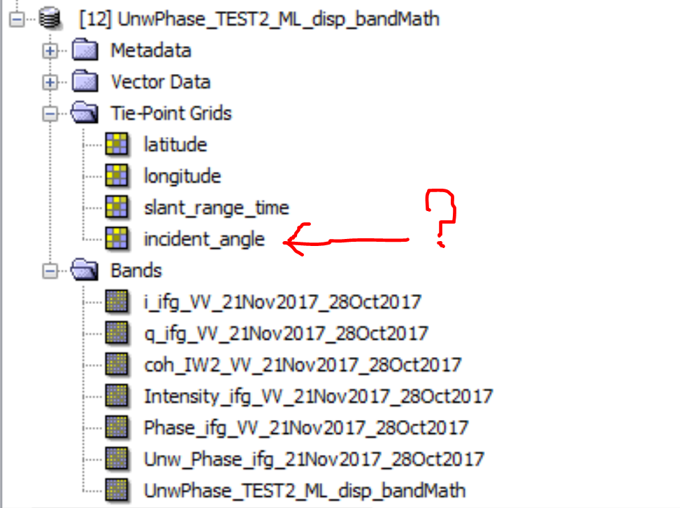
If so, I would disagree, in the example i’ve attached above the product is not terrain corrected and yet has the incidence angle raster.
Might you clarify this for me?
Thank you!
It is not published yet but you can do these steps in any gis. His TanDEM-X data had precise orbits but there was still a ramp indicating that there is a wrong angle estimated between both acquisitions.
Yes, there is an incident_angle band in Tie-point grids. When you perform Range-Doppler you can create Projected and Local incidence angle bands from it. I used local incidence angle for my map because this band seems less general and more informative for me than other possible incident bands. In my opinion, using incident angle before Range Doppler if everything will go smoothly, may and should produce the same (or comparable) result, because here we are dealing with just mathband calculations, not with the tricky SAR operations. I’ll check it in my spare time.
I’ve checked it. When I calculated Step1 before Range-Doppler using Incidence angle from tie-point, I received blank band. So, it would be better to work according to the workflow above.
Interesting… I carried out the band-math UnwPhase to displacement calculation with the tie-point-grid incidence angle band before terrain correcting and after and it produced the same result. Also results were very close to each other when using the projected, local, or ellipsoid-derived incidence angle. Oddly enough the results are strikingly different from the ones obtained using SNAP’s Phase To Displacement operator. Does anyone have an idea what kind of expression the operator uses? I was unable to find the answer in the SNAP documentation.
Sorry, I’m going to as a silly question. After all the exhausting work I’d done, I lost understanding - why do we have some value (not equals to zero) in a point where we assume elevation hasn’t changed? Where points 3 and 4 come from, what is the reason for their existing?
the unwrapped interferogram simply shows you the difference in distance to the sensor between image 1 and image 2. It has no reference yet. But at some point, the change should be zero (given that not the whole surface covered by your scene is sinking). You need to tell SNAP where this surface of change touches the ground.
4 Likes