A. Are these steps good and enough for backscattering?
B. As I know for backscattering we should use Sigma0 in calibration processing but when I use Sigma0, then I can not do terrain faltering. What can I do now?
C. What is the difference between Sigma0, Gamma0 and Beta0? Why does Sigma0 use for backscattering?
D. When I do terrain flattering, it coverts Beta0 to Gamma0. Why?
D. Frankly speaking, I just heard people do terrain flattering but I do not know why? Would you please explain for me?
Why not start from GRD data instead of SLC? Saves you a factor 4 in download size and you would only need to do step 2, 3, 5, 6, 7, 8 , 11. Speckle filtering should be after 5. Not sure what resampling does and reprojection is part of 7. Terrain flattening is a radiometric correction/normalization for non-flat terrain, but check the Small et al, TGARSS paper for details. I understand that it should work now in a similar way as in the paper (previous SNAP versions deviated from that).
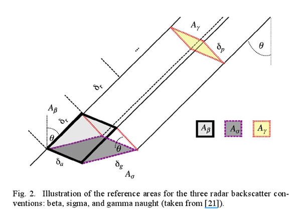
Please check the paper from 2012-TGRS-Improving PolSAR Land Cover Classification With Radiometric Correction of the Coherency Matrix, “The reference areas used within the , and backscatter conventions are illustrated in Fig. 2. Each convention employs its own definition of the backscatter reference area, placing it in: 1) the slant range plane itself ( with area ) the ground as modeled by an ellipsoidal Earth ( with area ); or 3) the plane perpendicular to the local look direction ( with area ) [26].”
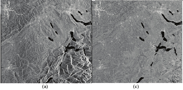
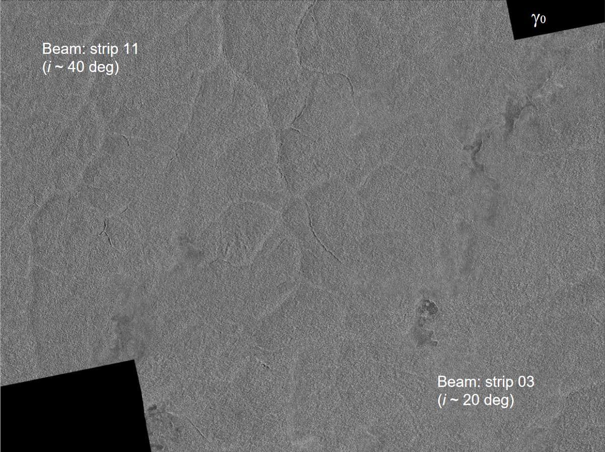
and 2009-TGRS-A Revised Radiometric Normalisation Standard For SAR, the figure above shows SAR image before and after terrain-flatten which removes the stereoscopic sensation.
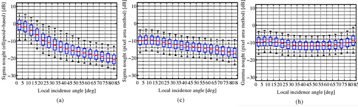
after the ideal radiometric correction, your radiometric variable no matter sigma/beta or gamma-naught, should not be a function of local incidence angle.
@ABraun @mengdahl
Does it mean that the Gamma0 and Sigma0 products provided by SNAP are now normalized according to the illuminated area (as proposed in Small et al., IEEE TGRS, 2011) rather than only the local incidence angle from the SRTM DEM?
@ABraun
So as I understand, the only benefit of using Gamma0 over Sigma0 is that the Gamma0 is terrrain flattened (as proposed in Small et al., IEEE TGRS, 2011) and the Sigma0 is not. Am I right? There is a lot of literature talking about the geometries of Beta, Sigma, and Gamma naught in terms of the reference plane but seldom did they highlight the benefits over one another. Is there any increasing order of benefit between Beta, Sigma, and Gamma naught, when the last two are normalized only using the local incidence angle?
What is quite clear is that Beta0 is the absolute radar brightness and requires no geometrical info. The main question that remains is how is Gamma0 better as compared to Sigma0?
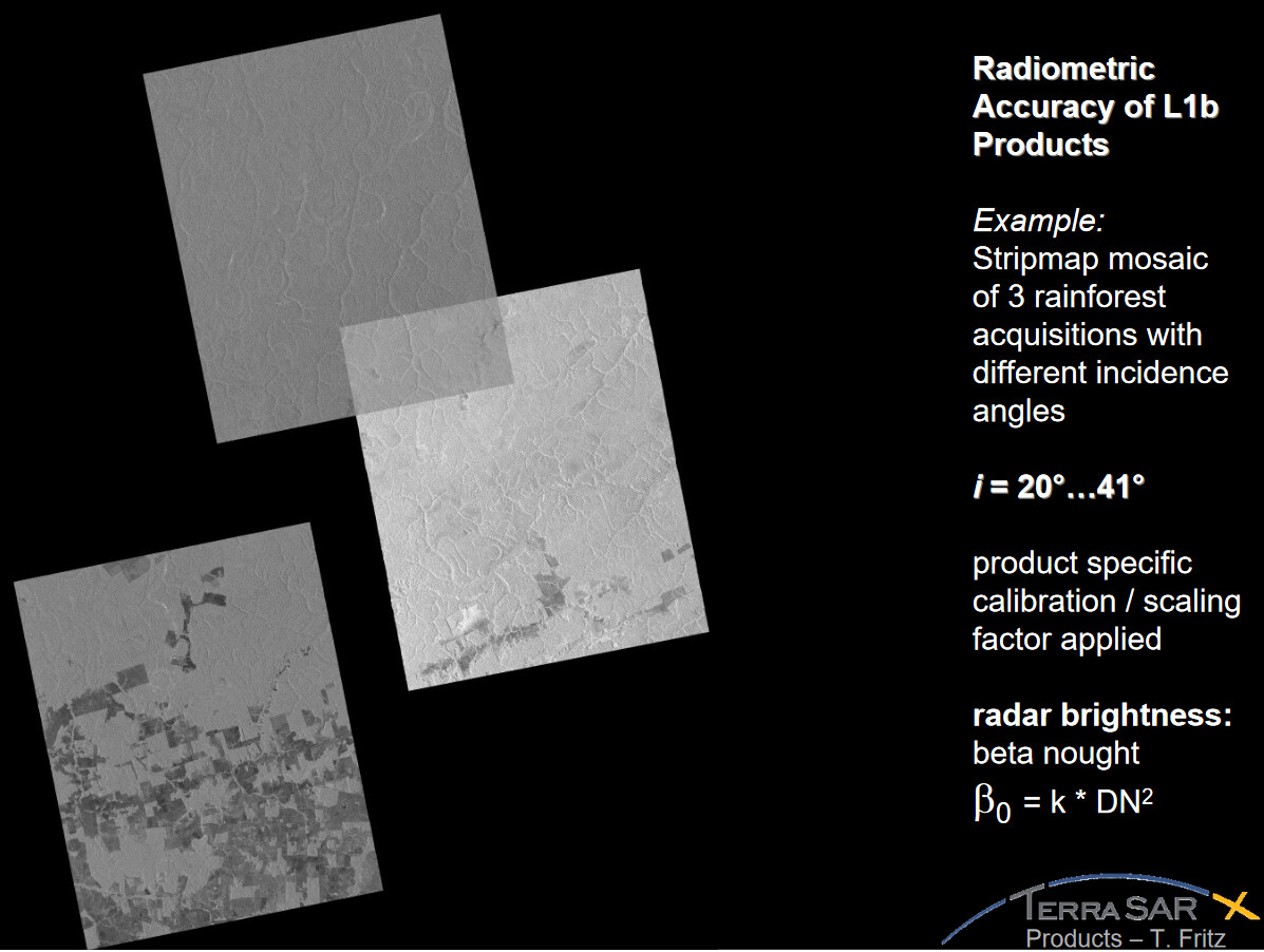
This was in 2008, before Small et al., IEEE TGRS, 2011, so the normalization is still local incidence angle based. The local incidence angle info came from a Geocoded Incidence Angle Mask (GIM). As per,
“A Geocoded Incidence Angle Mask (GIM) is available for the Enhanced Ellipsoid Corrected (EEC) product. The GIM contains information on the local incidence angle and on the location of radar shadowing and layover in a coded mask. The mask can be used for further processing such as radiometric calibration.”
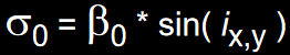
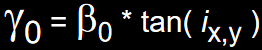
Here Gamma0 is presented as a ‘Radiometrically corrected Gamma0’. I am wondering how can a change of mathematical relationship from,
to
create so much of a difference with the visible seams between the mosaic, particularly when both are generated using the local incidence angle from GIM. At the same time it is interesting to question if GIM, which has info on the local incidence angle and on the location of radar shadowing and layover in a coded mask, has the same end effect as the normalization method proposed by Small et al., IEEE TGRS, 2011.
yes, Gamma itself is not necessarily terrain flattened, but this combination integrating the orientation and surface of an illuminated pixel was first introduced by Small in 2011. He called it Terrain Flattened Gamma to include the novelty.
As you said, anyone could easily calibrate to Gamma already before, but only as an angular correction.
To consider this mathematical difference, SNAP now lets you decide if you want to have Sigma or Gamma as output of the TF operator.
@ABraun
So if both Sigma and Gamma are available in the terrain flattened format, which one is more significant between the two? On what basis can I make a choice between the two?
Any comments on how the seam in image mosaic visible in Sigma0 disappeared in Gamma0 by merely changing the mathematical normalization factor but using the same local incidence angle as shown in,
It is half a dozen of one or the other. A lot of what people feel like they need boils down to what has been historically used in their scientific discipline or application.
With sigma a number of disciplines do what is called incidence angle normalization - to make all data look like it was imaged from a common incidence angle. This is not a perfect approach either.
Gamma is essentially a similar approach where it theoretically (not a perfect approach either) corrects for all geometry dependence. When there is no layover - the facet area integration should produce similar results to using local incidence and projection angles. Small, 2011 approach attempts to address issues with layover as well.