I was recently working with an S2 image over Beijing and I saw something interesting, but I could not really explain it.
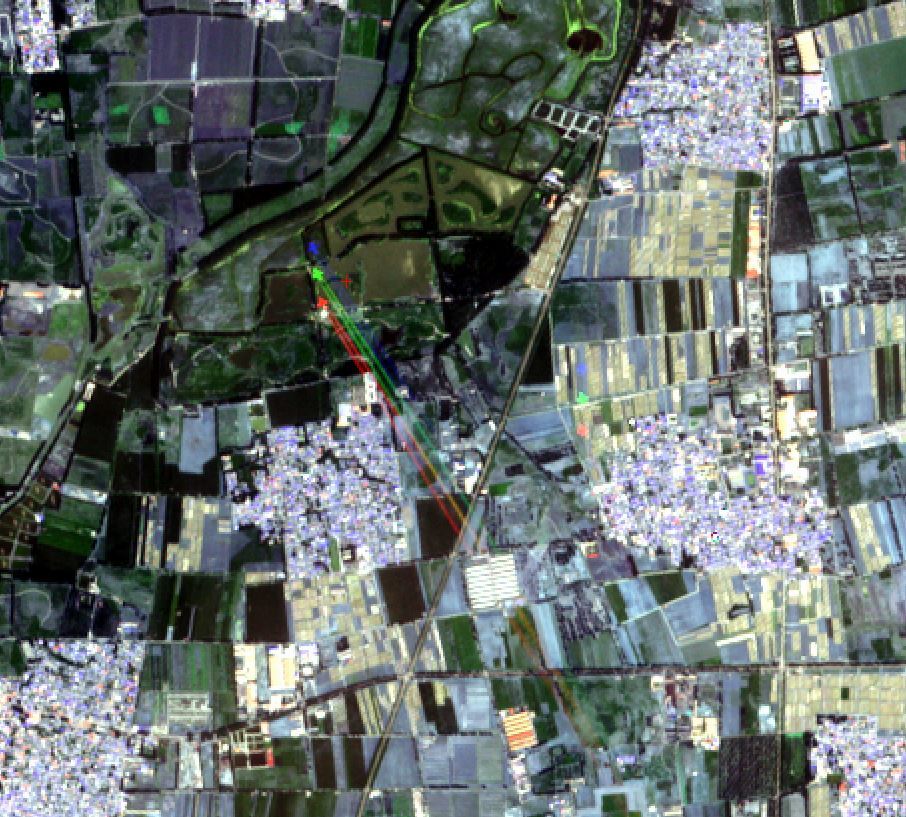
On that picture I can see an airplaine (I would even guess it is a fighter jet). I uploaded the image below. Could anyone explain
me why the jet appears so displaced in the RGB channels? Another thing: if you look closely, you will see that there is something which appears to be a second jet (on the South-East of the first jet). I am not sure if that is a fragment, caused by the other plane?
What are your thoughts on that?
This has been seen before, and is not a data issue. It occurs because the cross-registration of high altitude objects
(such as clouds and aircraft) is not possible. If you see the contrail cross a detector boundary, the colours become inverted due to the forward/reverse view of neighbouring detectors.
Hello Jan!
Could you give some any more detailed reference to the S2 MSI sensor planes geometry. I found only this (below). So I can offer next: there are really two plains … differens in colors may be if sensors geometry is not “same earthview beam” (sorry my english).
We deal with forest fire detection algorithm with S2 data and found some error detection with 2-3 seconds delay in clouds on one scene due to chess focal assambly detectos place (as in document below).
Hmm…
Can I ask you to check the Processing Baseline version of your product? The Processing Baseline Number (Nxx.yy) ican be found at the end of the L1C Tle folder, or at thend of the DATASTRIP name - i.e.
Ok, we download regularly here (these concrete scene): http://sentinel-s2-l1c.s3.amazonaws.com/zips/S2A_OPER_PRD_MSIL1C_PDMC_20160608T135039_R020_V20160608T064831_20160608T064831.zip
then – we just automatically convert from JP200 to geotiff. And sorry, we loose so long name of files and subdirectories. (amason as i know - just a copy of copernicus archive).
But why is surprise of clouds shift on image? - it is normal if we have a registration at detectors assamblies as in document (chess order).
Alexey
Yes. This is normal behaviour. There will always be a shift in the clouds between detectors because the detectors are arranged across the focal plane so that neighbouring detectors look in different directions (one forward, its neighbour backward, and so on). This results in different view angles
The differences in view angles are correctly handled s calibrated to give optimal results on ground via a numerical terrain model. However this processing cannot accurately cross-register images of clouds at high altitude.
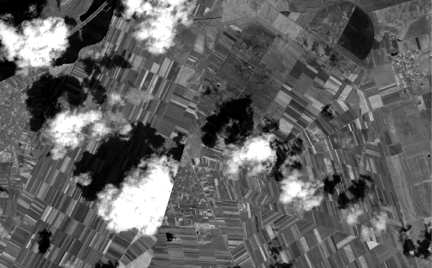
This is a screengrab of B12 viewd in SNAP, from T03WWQ, Orbit 005289, acquired yesterday over Alaska:
i noticed a similar disortion in another granule. The issue here is that not only cloud but also the ground level is disorted, so the error is not only coming from the across angle arrangement of the sensors. It’s actually another place that was stichted together…
Note the two parallel lines in the left and right part of the image:
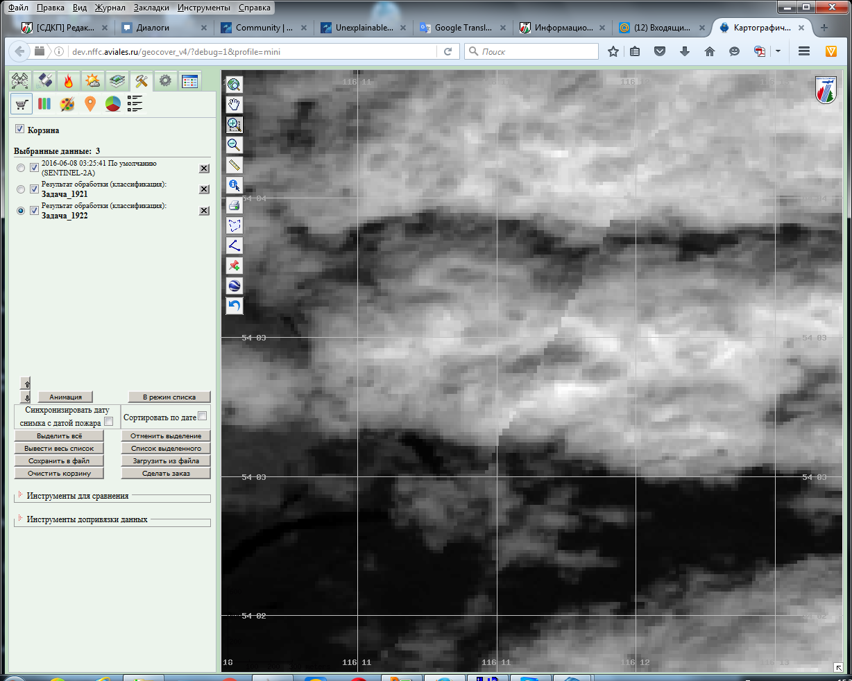
I have no any approvements! but on 20016/06/09 there were some stranges that lead to anomaly in a lot of false fire detections… it seems like channels data were mixed ))) But in our interface they look fine: pro-vega.ru/
Alexey
PS Jan, may be shift also - but we could not say accurately, There was no problem with data over Far East over Russia - the problems begun over Ural and continue to Easten Europe on 9-th of June
A Processing Baseline (02.03) was introduced on the 9th of June that caused a strong misregistration. @unnic’s screenshot - being onground - looks very much like this.
Products from this Baseline should therefore not be used
Hi Jan!
Sorry. I continue some qwestion about different geometric coregistrations with odd and even detectors at channels.
What is algorithm to compose (mosaics) detectors together? “linking line” has some disposal at channels 12 and 8a inspite they are the same surface resolution.
Sorry, but that’s not a question I can answer, I’m afraid. May I suggest you direct the question to eosupport@copernicus.esa.int where it will be passed to those better-placed than I to answer it.
No worries. Its you’re best shot at getting an expert answer
If you can take a screenshot of these linking line disposals, I’d be interested to see it.
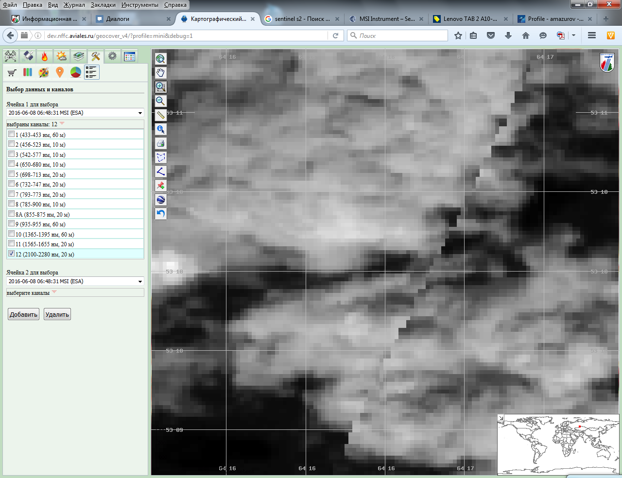
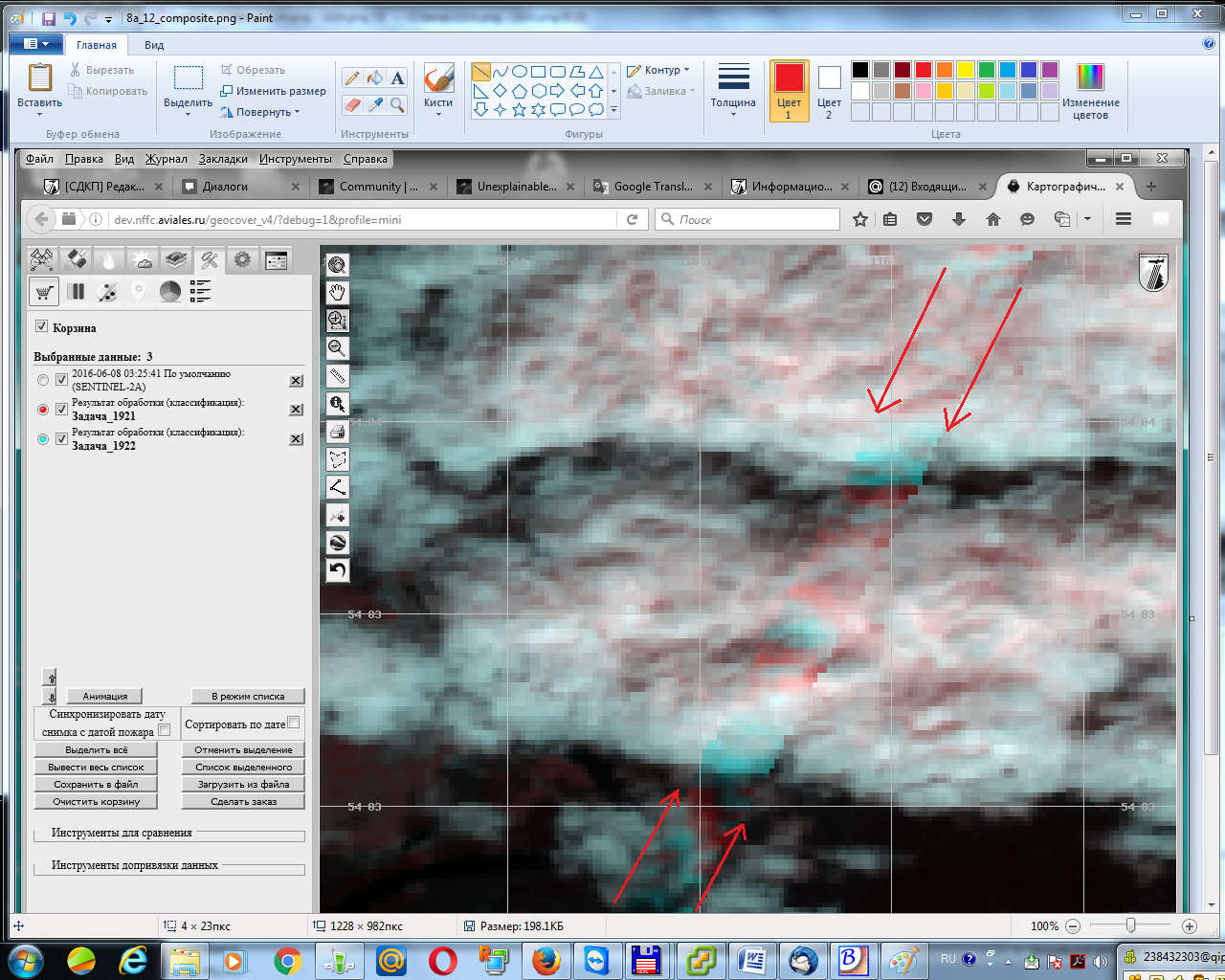
Jan! thanks for interest. Here they are - about 15-20 pixels diagonally one from one “linking line”.
two images (12 and 8a channels) from the same data set.
Hi Jan!
I sent my qwestion to support team, but get only status “open”. Do you have any idea whats the reason to bind different channels with different manner?
Yours,
Alexey
I’m not sure I understand your question, I’m afraid.
The two Bands you identify are obviously the same pixel size (20 metres spatial resolution https://earth.esa.int/web/sentinel/user-guides/sentinel-2-msi/resolutions/spatial). The neighbouring detectors ‘look’ in opposing directions - one northward, the other southward, but only by a small angle, which means it is not possible to accurately cross-register images of clouds at high altitude, and thus this effect will always be present.
Hello Jan!
I try again, sorry my bad explanation.
There are two images from 8a and 12 channels of the same region (exactly both of the same dimension), geographically identical.
Both have evident linking line from neighbore detecktor sets. But this “link” lines lie not on the same place at images. There is about 15 pixels distance one line from another. So on one image we may have cloud and on another clear due this difference in binding data form detector sets.
You may overlap images and see this (I try to show with screen shot)