Excuse me, we should edit and adopt these codes to use the InSAR results as input to model the earthquake? or they have tested in the case of using the displacement derived using InSAR?
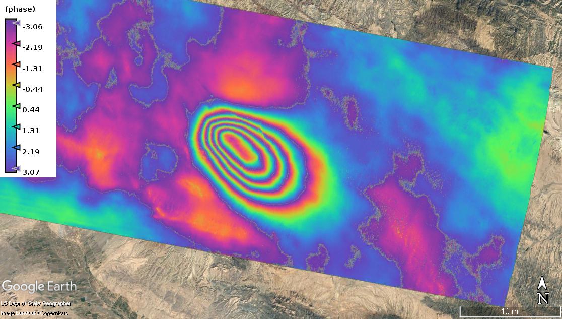
Thank you. Actually, I know my study area. There is near to the desert. So, I think we will not have a very big change in water vapor, as the most important element in atmospheric error. Do you have any idea to check the accuracy of this plot conceptually? for example by overlapping with topography?
I just know that phase is very sensitive to atmosphere and it doesn’t take heavy rains to disturb it.
But I can’t tell if the values are feasible.
Yes, for earthquakes it can be difficult to find a reference area where we can assume the deformation is zero. For all of the earthquake source inversion programs that I have used, the shift of the zero level is estimated as one of the estimate parameters for each interferogram in the inversion. If the earthquake is affecting a small part of your scene, you could assume the deformation is zero at a point far away as a reference, but atmospheric effects get stronger with distance so the reference area is likely affected by atmosphere.
1 Like
Thank you so much for your nice description. So, I need to be careful in selecting an area not very far from the earthquake area (center), because of the atmospheric effects.
Based on what you said about the source inversion programs, do not we need to set the interferogram and also displacement to a reference area before giving to model as an input?
Fault slip modeling involves estimation of a number of fault parameters, including the fault location and the amount of slip. You can add the estimation of an additional “shift” parameter for each interferogram in the inversion and avoid trying to set the reference area in advance.
1 Like
I agree, the water vapor in the atmosphere varies rapidly over the Earth. Depending on the local topography, there may or may not be a repeating pattern related to the topography.
Dear all,
I processed this study area in terms of using both VV and VH separately and got the following figures:
VV:

VH:
Based on these above figures, we cannot wait for a change in the results of using VV and VH polarizations. So, is it possible to use each of them for the InSAR app? 
Best regards,
Sayyed
1 Like
Is there any reason you specifically need to use cross-polarization for displacement estimation?
@qglaude Actually, no but I am thinking about finding a new thing in this area as innovation and also a test to understand the effect of cross-polarization for this app.
I guess it is always a good thing to be curious but be careful when digging into totally exploratory experimentations. From what I hear you’re trying things without having anything or goal in mind.
I cannot blame you because I always tend to go in this way too, but just wanting to warn you that it is a dangerous time-gated path with few benefits. I recommend you instead think about what is hidden in a cross pol information, what is its purpose and also make google schoolar research about related works. Then you’d be able to understand what are the benifits of using the cross polarization in SAR interferometry, and you will be able to better observe what are the additional information it will bring to you. Then your experiments are not just exploratory, but instead you have already something in your mind
I hope it helps 
Thank you so much for your kindness. You always behave nicely with others 
Before putting the post here, I searched in google and also in this forum about what I can get using the cross-polarization state like what @ABraun mentioned in this forum. I found that it is useful for the classification app. So, you can confident that I will search and read about my thinking before posting here 
1 Like
Since coherence is usually lower in cross-pol, the VH-result should be of lower quality, Therefore for DInSAR it does not make too much sense to double the processing costs by also including VH. The situation is a bit different for PSI (Persistent Scatterer Interferometry) as you will see some PS in the VH scenes that are not PS in the VV scenes, so including both can be useful.
3 Likes
Dear all,
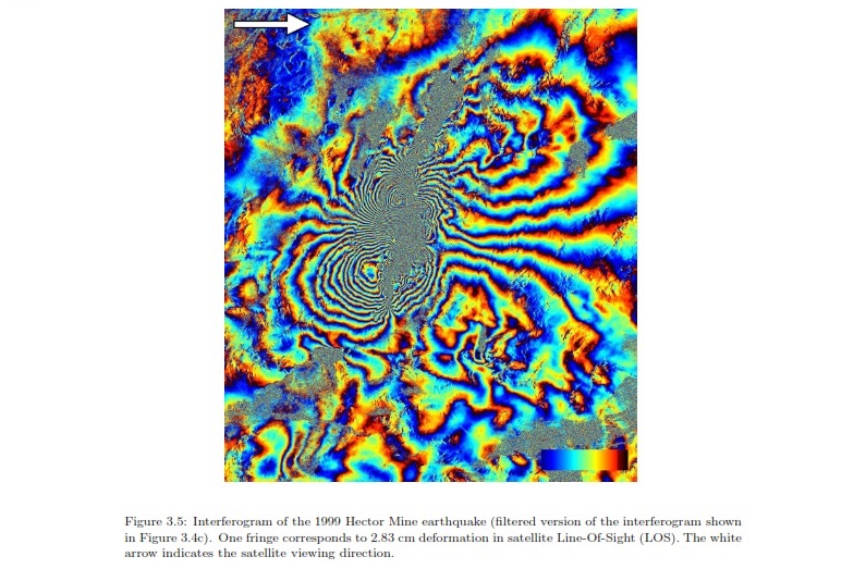
Excuse me, I read a statement in a thesis: “When the horizontal component of the satellite LOS is approximately parallel to the fault plane, a butterfly pattern will not be observed. Knowing the satellite LOS is therefore important when interpreting coseismic interferograms.”. Does it mean that when the value of dip parameter is zero (parallel to the fault plane), we cannot see a butterfly pattern?
This statement has been written about the following figure:
Best regards,
Sayyed
Dear Fielding,
I read more about your statements especially using the 3-D deformation in slip modeling. If I understood right, the 3-D deformation can help us to consider a more accurate initial value of fault parameters such as slip (amount of displacement) to solve the inversion?
Best regards,
Sayyed
No, this statement is about the strike parameter of the fault relative to the SAR LOS, not about the dip. If the strike of the fault is parallel to the LOS vector for a strike-slip fault, then you won’t see the butterfly pattern. This only applies to strike-slip earthquakes like the 2003 Bam earthquake.
1 Like
Having the 3-D deformation field is more useful for defining the fault geometry (strike and dip) than the amount of slip. If you already know the fault geometry from other information such as aftershocks or mapped faults, then you can estimate the fault geometry from that instead of from the coseismic deformation.
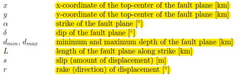
Thank you so much. I can find the some parameters such as Strike, Dip, and Rake through USGS or CMT but for other parameters, I think I need to try with coseismic deformation. I found that I need to define the following parameters for modeling:
Did you try to unwrap? In the legend I see phase not meters.
@hriston_bg Yes, I did it. These results, as you can see, are only the interferograms but after doing the unwrapping step, I saw that the displacement is not in the range of the meter.