Phase to Displacement Units?

if im able to process LOS for ascending and descending data how can i solve for the actual movement (vert and horizontal from this two LOS? can that be done in SNAP toolbox also? as i assume i’ll have two raster data result for two LOS

thanks again

I think this can be derived mathematically with vectors. You have the displacement and the angle at each pixel. If you make them a vector in both ascending and descending and add both vectors you get the resulting direction.

Please anyone correct me if I’m wrong.

1 Like

It’s a change of vector basis from LOS-vectors (+the orthogonal 3rd basis vector) to a new 3D vector basis (easting. northing. up). The formulas get quite involved, see for example:

https://www.researchgate.net/profile/Xiaoli_Ding2/publication/225604929_Inferring_three-dimensional_surface_displacement_field_by_combining_SAR_interferometric_phase_and_amplitude_information_of_ascending_and_descending_orbits/links/00b4952428c1a31364000000.pdf

3 Likes

good to see, thanks for sharing. I think this question was asked in here quite often but I didn’t have an answer or a document to refer to. But this seems to be a good approach but as you say, it’s not really trivial to get away from LOS displacement.

Hi there @ABraun , Earlier in this conversation @johngan had explained that the Phase to Displacement tool is used to convert the phase (radians) to LOS Displacement (meters). From there, the equation: vert_disp = (unwrapped phase * wavelength) / (-4pi * cos(rad(incidence angle) )) converts LOS Displacement to Vertical Displacement with the wavelength carrying the units. For Sentinel 1A data, 5.6cm is the wavelength for this satellite and should be used for the wavelength in this equation if you want a result in centimeters. From there, you need to have a known zero in a project area and use the value at that point to reach absolute displacement. You would simply subtract this number from the entire image to have an absolute displacement result. I tend to agree with this methodology, as I have practiced interferometry for some time and have used other software, however, I am new to SNAP and trying to get a good process in place.

Later on in this conversation you state that you shouldn’t use both the Phase to Displacement tool and apply the Vertical Displacement equation, you suggest to use one or the other and that they are essentially the same. Can you please explain why I shouldn’t use both and why @johngan may be incorrect here? I am having discrepancies in my displacement results and I dont’ know why. Somethng is wrong here? I am trying to figure out what the best recipe is for getting this right. Thank you very much for your time, I greatly appreciate you.

2 Likes

Hi dsmilo,

As ABraun stated, you can use either the SNAP tool for converting the phase into displacement or the formula. The results are the same. You do not need to switch between between the formula and the SNAP tool to compute the map displacement. If you want to use SNAP (phase to displacement), stick with it.
Bear in mind that phase to displacement in SNAP is in LOS geometry and not vertical displacement. Below, I have the results of a displacement map (LOS geometry) using both SNAP tool and the equation. On the left, we can see the results obtained by SNAP and on the right, the results obtained by using the equation (unwrapped phase * wavelength(m) / -4 *PI).

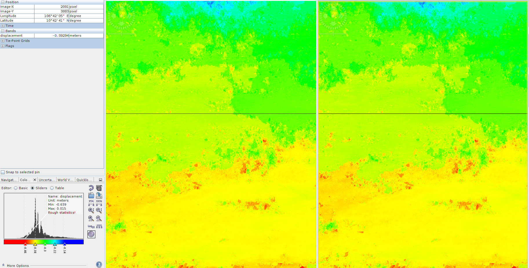
As we can see, the results are the same (the unit is in meters). The only difference is in the min values.
SNAP: min -0.645 max 0.015
equation: -0.639 max 0.015

8 Likes

Thank you @johngan for the clarification. I really appreciate you taking time to prove this. This makes perfect sense now.

hi @dsmilo im new in doing interferometry you mentioned “known zero in a project area and use the value at that point to reach absolute displacement. You would simply subtract this number from the entire image to have an absolute displacement result” how would i know where is the known zero in that area? this is my prob and can’t proceed as my values shows -.04cm to +.68cm how would i know where to get the zero to be subtracted to get the absolute displacement?

Thanks!

Hi @mauleon.fb you would want to look for areas of no change at all, like a mountain, for example. It’s best to choose an area that historically holds a trend of no change. You would know this by having a good historical understanding of your project area. Take a look at your interferogram and identify a few places that show no change. Then take a look at an aerial to see what’s there. Make the best decision based on your findings. Once you have picked a spot, you may want to have a historical look at the area to make sure it in fact has looked the same for a while to indicate that its a solid known zero. You can use Google Earth to view historic images, and also use any other data in the area that you may have, like survey data, ect. Once you are sure about your area, take an averaged sample of the area to get a good number to use for the subtraction to get absolute displacement.

2 Likes

@dsmilo thank you for your response. this provided me a good understanding of the process. Appreciate it big thanks!

Hi again. What is the more accurate data to use in terms of using Sentinel 1 data for DinSAR? 1. Two both ascending data, 2. Two both descending data or 3. One ascending and one descending data? I tried using both ascending and compared to 1 ascending/1 descending and I got completely different results. So I’m wondering which is the accurate method. @ABraun @mengdahl @dsmilo @johngan

that ascending and descending pass data produces different DInSAR results is little wonder as the displacement is described along the line of sight. So you basically look at deformations from two different angles and directions.
Please have a look at this topic as johngan explains it nicely:

Combining an image pair of ascending and descending passes for one interferogram shouldn’t work, flight direction must be the same.

3 Likes

Completely agree with ABraun. It is common sense to use only one direction of the platform in estimating the vertical motion. My experience with tracing landslide in NE Bulgaria was to select ascending orbit, because (as far as I know) S-1 satellites are right looking sothe expected motion is towards the sea and not vice versa. As previously said it is essential to have some preliminary knowledge about the processes studied.

2 Likes

Here’s a new pertinent reference:

3 Likes

Yes, I also completely agree with @ABraun. Both aquisitions need to have the same angle and path direction for both scenes to be statistically comparable and analyzed.

hai @dsmilo , according to your suggestion about zero point on project area i want to ask, if my interferogram is want to know the displacement of mount eruption, then what point i have to choose? bcs my project area is tropical country (covered by vegetation), instead my radar source is sentinel-1 which carried band C. thanks before!

Hi. I have a quastion, when i calculate vertical disp as you mentioned in your shot, after applying geometric terrain convertion, my disp map appear black and white!! What can go wrong during band math calculations, i dont know!!pls help me

Hi @zealandia_sarah, I am having a little trouble understanding your question. I think you are asking where to find your zero point in such a high vegetative site. In my opinion if you can’t find an area that has no change to help you create a benchmark for all your data, the amount of error will go up in your results. High vegetation can create a whole lot of decorrelation which can skew your results pixel by pixel. It would be hard to call your results reliable. Do a little more geographic research in your AOI and see if you can find a feasable zero benchmark. You can also use other data to help. Try to see if you can find survey data, well data, contour data from similar time periods to help orient your dataset. Are you trying to track the change in the ground under the canopy or is there a bare earth or near bare earth space that you are trying to detect change at?

You always want to apply the geometric terrain correction last. You want to apply vertical displacement calculation after you import you unwrapped image back into SNAP. Order of operations is really important here. Remember that when you orient your image using geometric terrain correction, you are changing the units from radians to meters. Your image is born in radians and all work done to your image in SNAP needs to stay in radians until you are done. If you terrain correct your image that changes your units to meters, then you apply a tool that works in radians, you will have some messed up results. Hope this makes more sense.

1 Like

@zahra0729: Did you have a look at the histogram or the image statistics if the values are still ther? Maybe you just need to refine the colour manipulation.
Edit - solved here: Phase Unwrapping to Vertical Displacement