Hi there!
I’m new to satellite image processing and since few days ago I’m trying to understand as much as I can. My goal at the moment is to extract a large number of polygons from a GRD product but before reaching that point I’m facing a somewhat silly issue and I believe is because I don’t fully comprehend how the data should be processed.
In first place for testing purposes I’m doing a subset of the product that I initially downloaded, I do this because I don’t have enough processing power and my machine literally dies, so subsetting is a must step for me. Then if I tell SNAP to render a RGB image (taking the following components: Red = Intensity_VV, Green = Intensity_VH, Blue = Intensity_VV / Intensity_VH) I get this image:
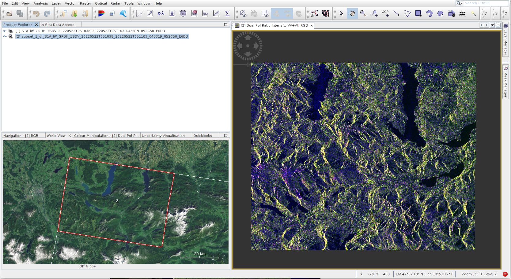
Which is not quite ok as the image seems to be mirrored in the horizontal direction. Then I decided to look up a bit of information about how to correctly get this and I found this post: https://forum.step.esa.int/t/sentinel-1-data-preprocessing/11576/27
In there, the user “ABraun” in his 12th post shows first doing a calibration and then a terrain correction. Note there how after calibration he actually gets the image vertically mirrored (similar to what happens to me the other direction). Then after doing a terrain correction the second image in that post message seems to be corrected as expected.
In my case this is what I’m getting after performing those steps:
- From the top bar menu I select Radar → Radiometric → Calibrate. From the Calibration window I select both VH and VV and “Output sigma0 band”. The resulting RGB image (taking the following components: Red = Sigma0_VV, Green = Sigma0_VH, Blue = Sigma0_VV / Sigma0_VH) after applying this step looks like this:

- From the top bar menu I apply the terrain correction: Radar → Geometric → Terrain correction → Range-Doppler Terrain Correction. These are the parameters that I’m using (default ones):
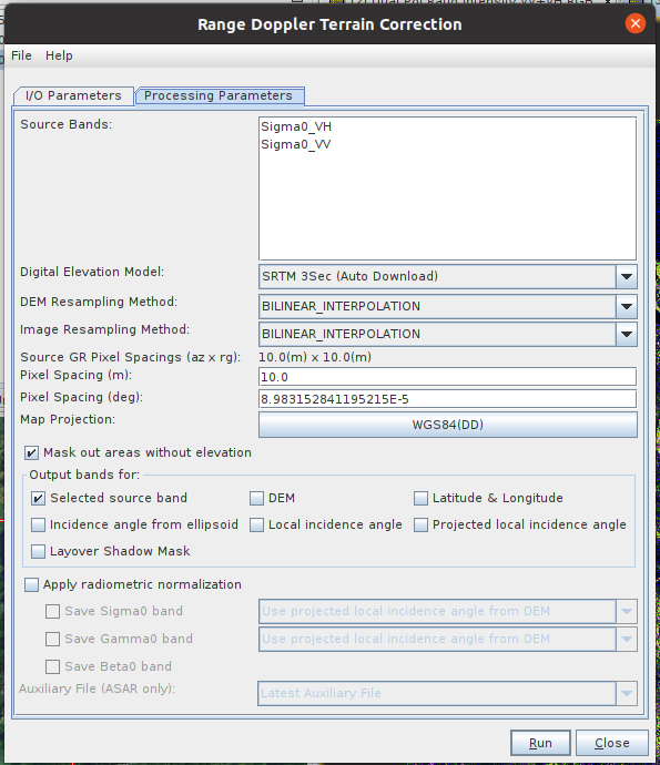
- Generate the RGB image using Red = Sigma0_VV, Green = Sigma0_VH and Blue = Sigma0_VV / Sigma0_VH I get this image:
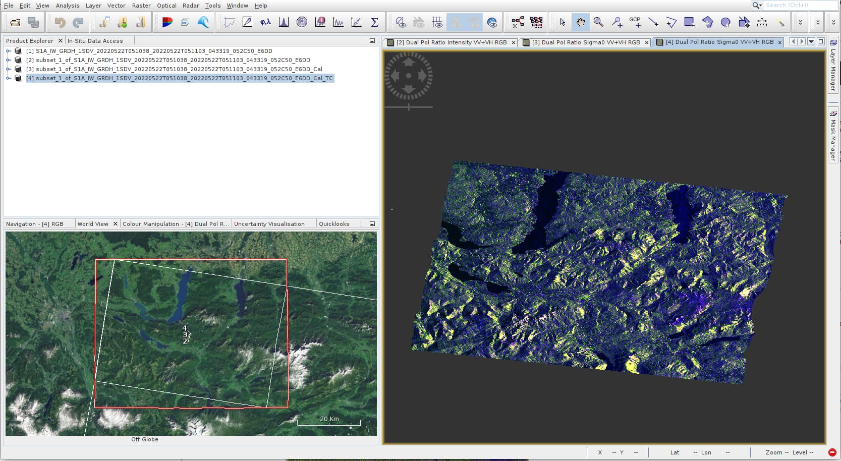
So, if I compare this final image with the second image from the post I mentioned earlier they definitely look different, mine looks like a different projection. I truly don’t know what I’m doing wrong but if someone could point me in the right direction much appreciated. I’ve also tried something different. From the “Graph builder” I do see a “Flip” operator (for some reason that I don’t know this operator is only available from the graph builder, at least in the snap version I’m using). So I added the operator and tried applying it to both the original subset and the calibrated subset products. This is the result:

Now the image orientation seems to be correct but its pixel values look like inverted. At this point I don’t know what else to try.
Finally I’d like to ask a silly but important question to me (again, forgive my ignorance on the subject). What do actually each pixel from a GRD product represent? For example what information is a green pixel, or a dark or a blue pixel telling me? I’m asking this because I’ve read many things and definitions but I can’t find a clear, simple and concise answer.
Thank you very much for your help,
Lucas.