Radiometric & Geometric Correction Workflow

Hi @ABraun,
I need to find some trihedral corner reflectors by Sentinel SLC imagery.
So, to do this, is it correct to follow your procedure for SLC data?
Thanks in advance.

yes, the terrain correction is the most important part because it produces geolocated pixels. You can also try the SAR simulation terrain correction which is often even more exact, but you can compare both.

1 Like

Okay, I try the SAR-Simulation Terrain Correction and then I will compare both.
In your opinion, for find a corner reflector, could be it useful to convert linear to db? If yes, at which step is it okay to do it?
Thanks again @ABraun.

The conversion to dB should always be the last step.

1 Like

Hi everyone,
to find my corner reflectors by S1 SLC, I have tried to do this workflow:

  1. TOPSAR-Split (VV polarisation)
  2. Apply-Orbit-File
  3. Calibration (output beta0 band)
  4. TOPSAR-Deburst
  5. Terrain-Flattening (default parameters)
  6. Speckle-Filter (default parameters)
  7. Terrain Correction (default parameters)
    Then I covert the gamma0 linear to dB.

But I have some questions about this workflow.
I see some papers that use sigma0 band instead gamma0 band to find the corner reflectors, so to do this I need to select as output the sigma0 band in the step 3 and to delete the step 5 (because it converts sigma0 band to dummy); first quesiton: which is the difference between gamma0 and sigma0 and which is better for my goal?

Second question: @ABraun I’ve tried to use SAR simulation terrain correction instead terrain correction, but the graph builder show the following error message: “Source product should include a simulated intensity band.”. Do you know why?

Every suggestion is welcome, thanks in advance.

please have a look here: Difference Sigma, Gamma and Beta nought?

are you sure you used this tool?


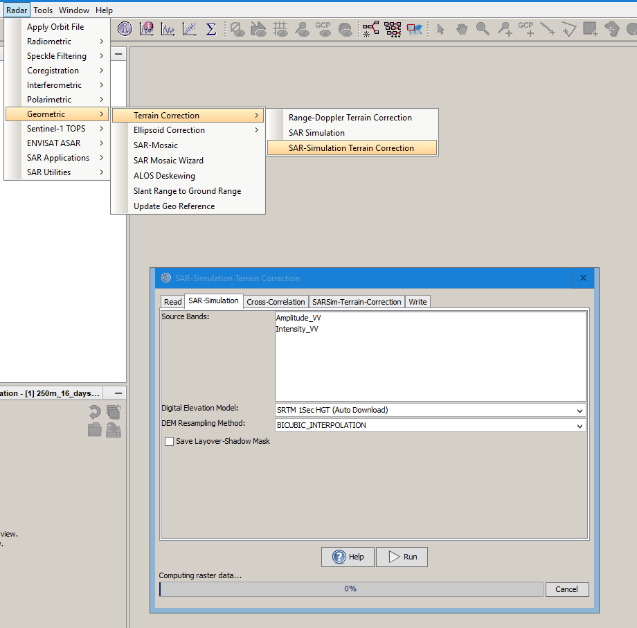
Because actually, simulation of an intensity band is part of the operator.

1 Like

Technically speckle-filtering should take place before TF so you should swap 5. and 6.

1 Like

How about the “Border Noise Removal” discussed in the article below?

I wouldn’t consider it mandatory, only if you have this kind of noise and want to get rid of it.

Hello.

I tired doing the SLC steps for generating gamma0 bands for VV and VH. However, the resulting bands are empty. Do you know any further step I need to do for this?

Thanks!

after which step is the product empty?

After range doppler terrain correction
here’s the screenshot:

Are the images OK of after the TF step? Empty images in TC sometimes result from missing DEM issues.

checked the results of TF and it was empty too… I found the problem now, wrong DEM.
Thanks a lot!!!

Hi, thanks for your explanations and links, they really helped me.
Could you please link the source when specifying changes like this:

" NOTE : Since SNAP 8, conversion to Beta0 prior to Terrain Flattening is no longer required, because it has been integrated into the TF operator."

Because I think this has not been implemented yet:


I’m using SNAP 8

Best,
Ognjen

It’s possible that the help menu hasn’t been updated yet(@jun_lu), but the issue is marked as resolved

Yes, but it says “Fix versions: 9.0.0.0”
image
Does it mean it won’t be included unti SNAP 9 or maybe I misunderstood?

According to my understanding, this is already included in the current version. At least I have tested with SNAP 8 and it worked.

For some reason the functionality is not in SNAP 8. We will issue a module update as soon as possible.

You might consider “forcing” beta0 calibration as preparation to terrain flattening, to avoid follow-down errors.