Have you tried another DEM for Terrain Correction? Maybe Copernicus 30m
Thanks for the quick response. I will try and let you know if it works or not.
It seems that the snap does not directly support copernicus 30m. Should I use external dem then and download the copernicus 30m dem from sentinel hub api @ https://docs.sentinel-hub.com/api/latest/data/dem/ ?
It should - did you get an error message?
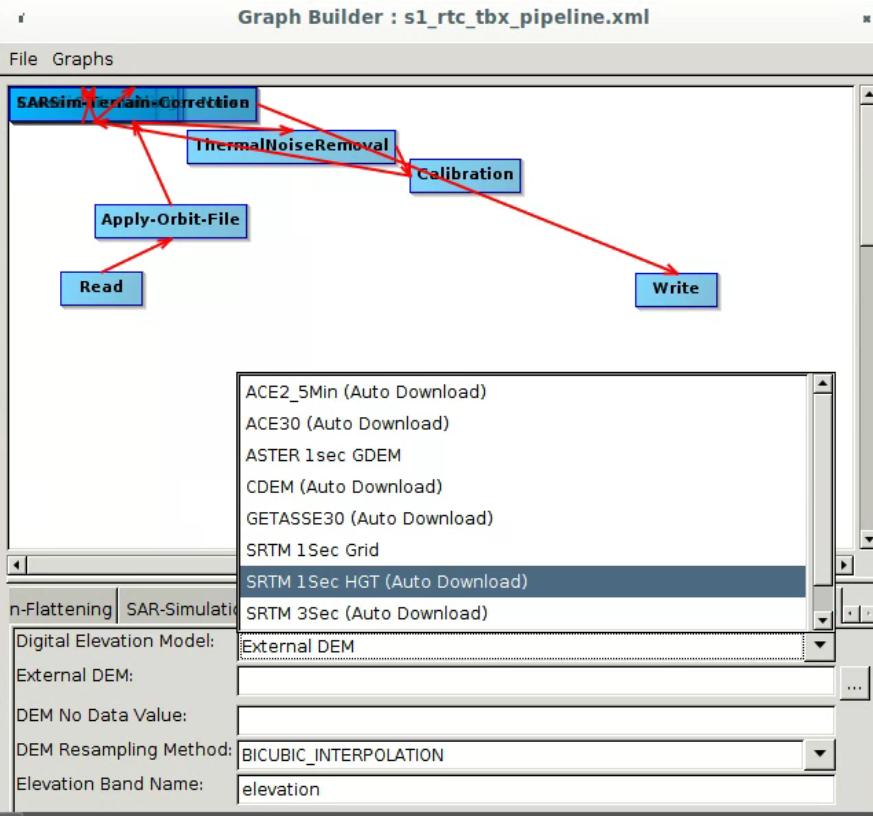
No, in the snap UI, graph builder, when I try to add node “add elevation” the raster dem the dropdown does not contain the string for copernicus dem. I have attached the screenshot for your reference
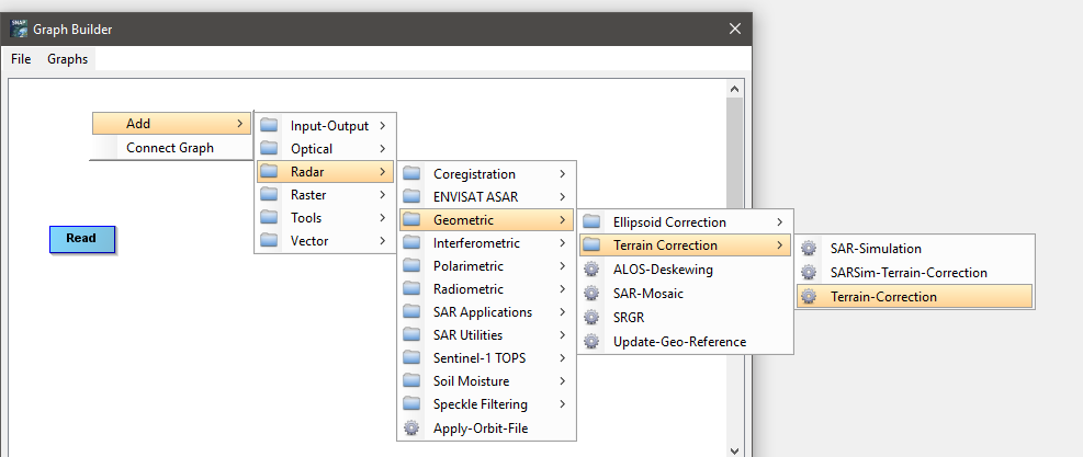
Sorry, I didn’t see that you were using the SAR Simulation Terrain Correction. Please try the Range Doppler Terrain Correction instead for a test.
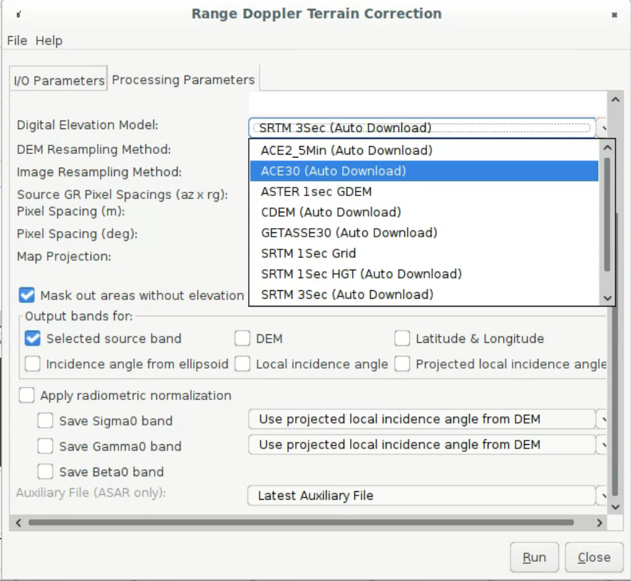
I did not get the option to create node for Range doppler TC in the graph builder. I also tried to run it manually by selecting it directly from the radar menu option but I could not see the copernicus dem in the dropdown of the dialog of Range doppler TC. I have attached the screenshot for your reference. Please advise.
(I’m working with Manoj, the original poster).
I ran the Terrain Flattening + SarSim Terran Correction flow in the UI using DEMs SRTM and Ace30 (the toolbox is updated to 8.0.8). As Manoj reported, the results are shifted relative to the old image and to the basemap, but each is shifted in a different way:
https://code.earthengine.google.com/7b406cddb7f23d3b5a147c97149e28cb
(you can uncheck some layers in the Layers panel to see them individually)
I tried using the Copernicus DEM, but the TF step throws errors:
COPERNICUS DEM 30m
Type: OperatorException
Message: 2549
COPERNICUS DEM 90m
Type: OperatorException
Message: java.lang.ArrayIndexOutOfBoundsException
The image is S1A_IW_GRDH_1SDV_20211003T155422_20211003T155447_039957_04BA98_2E2D
. The shift is easiest to see over water bodies.
If you are not signed up for Earth Engine, you can see the layers here:
https://simonf.users.earthengine.app/view/s1-tf-shift
Hey, after reading throughout the various posts, I got a bit confused and some things remained unclear to me. I plan to process years of Senitnel-1 IW GRD data for crop classification. My AOI is covered by full IW scene, so I intended to use full image (incidence angles from 30 to 46 degrees), and the area is quite flat.
I foresaw these steps:
- Apply Orbit File
- Thermal Noise Removals
- Border Noise Removal
- Radiometric Calibration
- Speckle Filtering
- Terrain Correction
- Conversion to dB
I saw people discussing about Terrain Flattening and(or) square cosine incidence angle corrections on forum and in papers. I was wondering if these two are of significant importance to such a task (crop classification) and if I should perform the one/the other/both or none?
Thanks
Terrain flattening makes sense unless your area is close to being flat.
Thank you for answering. Is there any relevant benchmark when we consider an area to be close to flat or not for TF?
Any opinion on SCC for Sigma0?
Well to be safe Terrain Flattening should be performed IMO, it will correct the part of the incidence-angle variation caused by local illuminated area.
1 Like
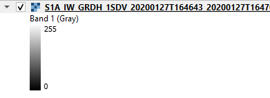
@ABraun Please help, can anyone tell me why my value range on RVI is from 0-255 and not from 0-1? How do I get the range to be similar to NDVI? I’ve noticed that (everyone) else managed to get the range from 0-1 (approximately).
I have followed all of the pre-processing steps explained in this thread.
I used the 4VH/(VV+VH) formula in band math
Thanks!
probably because you exported thte data to GeoTiff. Please have a look at the instructions and directly read the product from SNAP into ArcGIS: Export of products from SNAP
I have a weird issue when I try a terrain flattening workflow in the Netherlands area.
The data is an ALOS2 1.1 quad-pol data, and the workflow is as follow:
- Radiometric calibrate → create beta0 virtual band
2)Radiometric Terrain Flattening
3)Geometric Terrain Correction → Range Doppler Terrain correction
The result I get looks like data along what appears to be diagonal lines and no data in between (see image)

When I don’t use Terrain Flattening (stage 2) the result looks fine.
Also, this workflow worked for me with the same type of imagery around the world (South Africa, Scotland), and it doesn’t work for several images in the Netherlands.
I’ll apricate any ideas for the reason of this issue.
Thanks