From my point of view, you could avoid the merging afterwards, as the coherence must be computed at subswath level and there is not a real need to merge them. From my point of view it is a personal decision as you can work perfectly at subswath level.
Great! I’ll definitely have a look at those resources. So if you’d plan to look at coherence time series, what’s the best way? If you coregister each image pair separately, that would yield highest coherences, but coregistration of all the different coherence images would not be perfect… If you choose one master and use that for coregistration along the entire series, there’s the temporal decorrelation problem?
And regarding merging; it depends a bit. If the final coherence output of the subswaths is converted to geotiff and these subswaths are nicely aligned, I guess it’s indeed not needed. But what if there’s artefacts at the borders…
Hi @kristofvt
Well, probably this would need a deeper discussion, at it is quite specific.
Regarding master, a easy/fast solution is to get the master in the middle of the scene and coregister all the other images with this. If you plan to do short term coherence analysis, you can get separate pairs and verify afterwards that after doing the TerrainCorrection all images are aligned or not. From my experience in my area of interest the images were nicely aligned after the Terrain Correction.
There is still another solution, and If I am right, it is still not available within SNAP, is the multi-master interferogram. This is problably what you may need.
Regarding artefacts at the borders, they will probably be. Please check it as well. For the GRD you could apply the Border Noise Removal, but probably you will need to merge them. It will be interesting to see that if it may be requred or not. Maybe @lveci can say something more precise in this regard.
It looks like this issue is still open, in terms of creating a stack of S-1 interferograms coregistered to one master (what @Tomcater was attempting and I think what @mdelgado refers to as a multi-master interferogram?). I ran the python wrapper scripts from the snap2stamps package, which runs very nicely and smoothly (thanks). This creates a series of interferograms with one single master. I do not have access to Matlab or Gamma to continue with StaMPS, unfortunately.
Failing the ability to run back-geocoding/ESD on more than two images, I created a batch of back-geocoded/ESD registered image pairs, from a time-series (all in the same rel-orbit, location etc.), all with the same master (i.e. master-slaves as mst-slv1; mst-slv2; mst-slv3 etc.). I thought I could be clever and replace the .img and .hdr files such that data from slv1 in pair one becomes mst in pair two. I encountered some problems with the datatypes, so I converted slv1 data from flt32 to int16 and modified the .dim file.
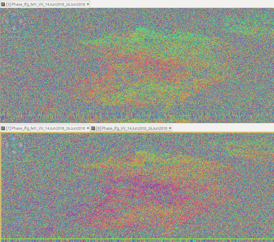
I managed to ‘trick’ SNAP into generating an interferogram from slv1-slv2 in this way, but I end up with some very strange results (image below). On the left is the first mst-slv1 image, in the middle is slv1-slv2 and on the right slv2-slv3. I am almost certain that this is because the flat-earth phase removal is using the wrong metadata. However, on the second row are the interferograms without flat earth removal and the results are not as expected either. Do people have any suggestions for which parts of the metadata I need to adapt to overcome this, or am I overlooking some fundamental aspects of SNAP/S-1 data/InSAR that would make this a pointless exercise?
Thanks, James

2 Likes
You can use the Matlab 30-days trial license. It has all the toolboxes needed to run StaMPS.
For multi-master I mean the master image for which all slaves should be coregistered before doing interferograms among themselves. Slv1-Slv2 once done first Mst-Slv1 and Mst-Slv2.
I hope this helps
could it be that although the rasters are slave1 and slave2, the orbit information in the metadata (*.dim) could still result from the old pair (master and slave1) and this causes the ramps in the interferograms?
Thanks, that’s what I thought you meant by multi-master. I will try the 30-days trial license, good idea.
James
Thanks, I suspect that might be the cause. The next question is if it is feasible to switch the orbit information in the .dim file to the slave1 orbit information. The coregistered stack .dim file contains information that is produced from master/slave orbit calculations (e.g. baselines etc.) which may be necessary and overly complicated to replace. I will have a go and report back.
James
I discussed this quite extensively here: Interferogram averaging for DEM generation
You might want to have a look at it, mengdahl mentiones the role of the baseline here, and I tried some approaches but wasn’t successful.
Let us know if you find a way that works. Even if it involves much manual labor, this could be automated later by a python script, for example.
1 Like
I’m getting more sensible results from using a .dim file created by back-geocoding and ESD processing slv1 to slv2 (where they are named mst and slv1), and renaming the .data, .hdr and .img files to match it from the slv1 and slv2 files which had been coregistered to the first mst file. This means that a lot of extra processing needs to be done: for each image pair, except the first mst-slv1 pair, you need to generate an additional back-geocoded, ESD coregistered stack to obtain the necessary .dim file. The processing chain for a slv1 to slv2 interferogram coregistered to a different master is therefore, for three images [mst, slv1, slv2]:
- Apply orbit files and select swath (TopSAR split), bursts and polarisation for each image
- Produce back-geocoding and ESD stacks for
–Mst and Slv1
–Mst and Slv2
–Slv1 and Slv2 - from the Mst-Slv1 stack .data directory move the Slv1 q and i .img files to the Mst-Slv2 stack .data directory, replacing slv1 to mst in the filename, and converting from float32 to Int16 and byteswapping (for some reason gdal swaps the endianness when it writes in the ENVI format) - these are the commands I used, but with more appropriate filenames:
gdal_calc.py -A slv1.img --A_band=1 --type=Int16 --format=ENVI --outfile=mst.img --calc=“round_(A,0)” --quiet --overwrite
gdal_calc.py -A mst.img --A_band=1 --type=Int16 --format=ENVI --outfile=mst.img --calc=“ndarray.byteswap(A,inplace=True)” --quiet --overwrite
- copy the .dim file from the slv1-slv2 coregistered stack to replace the mst-slv2 stack .dim file, and rename the mst-slv2 .data directory to the same name as the slv1-slv2 .data directory
Keep close track of directories and files as there is a lot of file and directory renaming going on, so it would be easy to get confused.
3 Likes
I had started to compare the .dim files from the mst-slv2 stack and the sl1-slv2 stack in order to parse which elements should be kept from each to preserve the correct image and orbit characteristics, when I realised the above might work. However, I imagine there are still some important metadata elements that have been lost, and if any of the images have a different size there will be complications.
interesting. Do the interferograms look better after the replacement of the dim file?
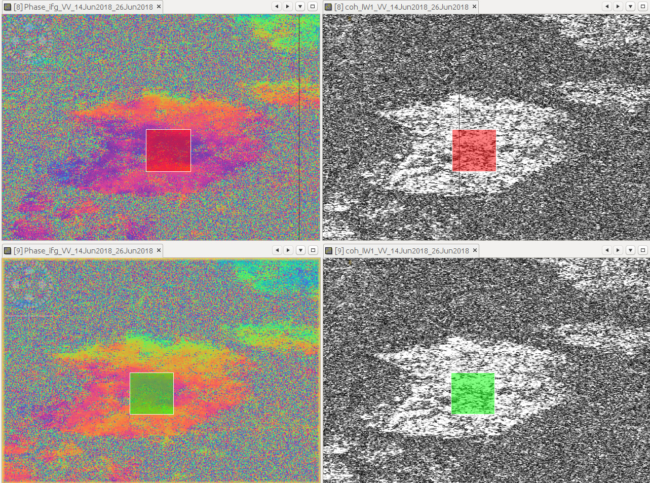
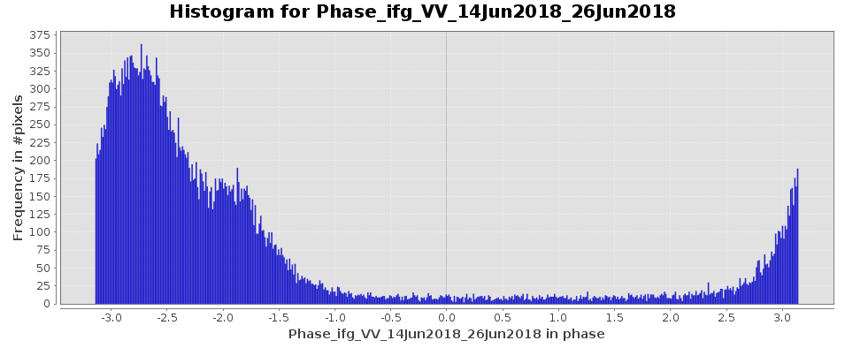
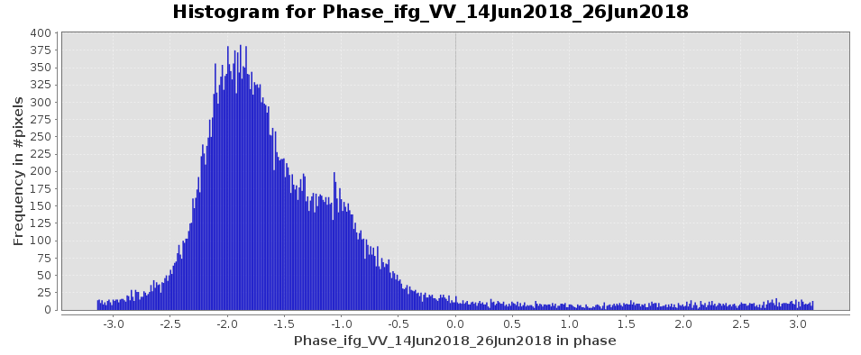
See below: The top figure is with the slv1-slv2 coregistered to slv1 (the usual, easy method), and the bottom is slv1-slv2 interferogram both coregistered to a different mst (my method described above).