Currently, this is the best option available. You can also plot the displacements of the single dates (pairs) of a pixel along a graph.
An example is given at the end of these slides: https://eo-college.org/resources/insar_deformation/
i am affraid there is no pdf available for deformation
you have to register (free) to download the materials.
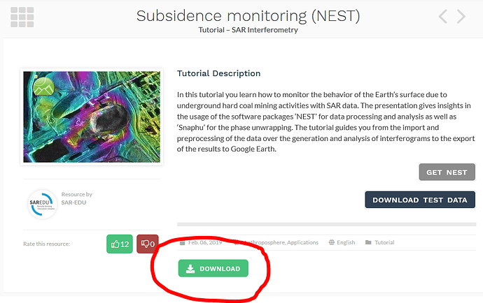
The download button will then appear at the bottom
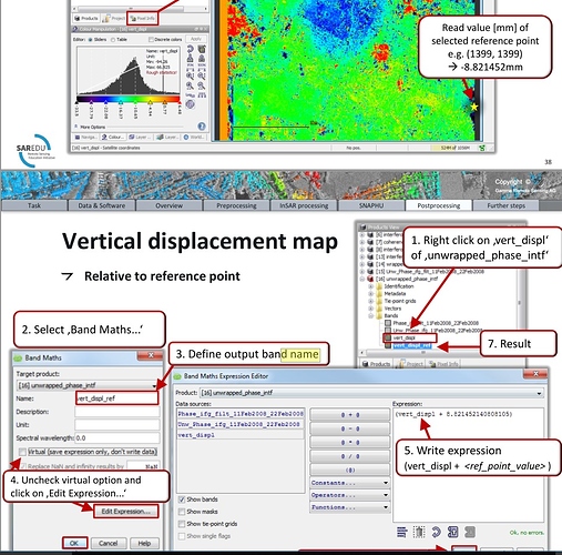
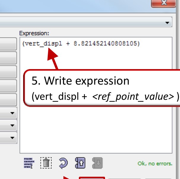
@ABraun can you please tell me why we have to add the reference point value and vertical displacemnt, in INSAR tutorial by Dr.-Ing. Diana Walter.
Also, does the sign of the reference value is important or not???
I’m sorry to get a cross this discussion, but would you please to share the title of this tutorial,
@falahfakhri please follow below link to download the tutorial after signing in to the website.
https://eo-college.org/resources/insar_deformation/
we have discussed this here:
Thanks @ABraun i already read these topics. One thing which is confusing me is the “+” sign in the tutorial slides. As per you discussion in various topics regarding the Vertical displacement you have mentioned to subtract the value of pixel where no deformation happened.
HI @gomalhunzai,
In the tutorial you went through, the value that has been selected as a reference point is -8.821452 (negative number). The subtraction is as follows: unwrapped_phase - (-8.821452) which becomes +. Lets substitute the unwrapped_phase with a subsidence value, 8mm - (-8.821452mm) = 16mm.
Instead, what we can do is 8mm + 8.821452mm = 16mm
@johngan then how we can say we have subtracted the values???
The value is doubled now.
The subsidence values you see on the final map are relative (master image relative to slave). In order to derive the absolute subsidence, we need to find an area in our relative subsidence map where we know that the subsidence is zero. Let’s say that you got GPS measurements for an area that you know no subsidence was occurred. You locate this area on your unwrapped interferogram and extract its value which happens to be -8.821452 (remember, this is relative).
Hence, we have the following: unwrapped_phase - (-8.821452) which becomes -8.821452 - (-8.821452) = 0
So, this is the area with a zero absolute displacement. By applying this value to the whole image, we can find the absolute subsidence
@johngan i am afraid that we subtract the relative or reference value from the image with vertical displacement. As shown in this picture.
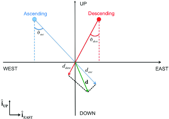
The SAR sensor makes observation in Line of Sight (LOS) direction (this is the SAR geometry) as shown in figure below:
Fig 1: LOS direction
Hence, whatever measurements we do, the results are going to be in LOS direction. In order to derive subsidence in vertical direction (we assume that the subsidence occurred vertically and not east-west), we need to do some trigonometry. So, in the equation given in the tutorial you have read, the cos (theta) is added to the equation in order to get the results in vertical displacement and not in LOS. The displacement values though, are still relative (but in vertical direction not in LOS), which means we still need to subtract a value of zero dsiplacement to get absolute values.
I have made my interferograms and recently, following this thread, I began to generate my vertical movement. However, after filtering Goldstein, I make a geometrical correction, cut, and unwrappening the phase, in this step the information of the angle of incidence (first image) is lost.
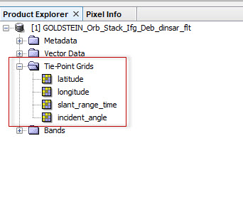
so, in the step of terrain correction I have selected the following boxes

But at the time of calculating the vertical variation, the data “incidence angle from ellipsoid” (which is the one that should be used according to the recommendations) becomes an independent layer. It is right?
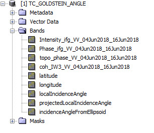
Thank you
@johngan so nice of you for explanation. it helped me very well  Just last question about processing step "Subtracting the ref value from vert_disp is correct or not?? coz u mentioned about unwrapped phase in previous post.
Hi @gomalhunzai,
It does not matter whether you subtract a value from the unwrapped phase or from the vertical displacement map. Our goal is to find an area around our AOI with a zero subsidence, which is going to be our reference point. So, you locate this exact area either on your unwrapped phase or on your relative displacement map and subtract the corresponding value. So, this area that has been substrate will have the value of zero.
Hi,
You should use the formula for vertical displacement first and then you perform terrain correction as your final step
Thanks for your answer, I had many issues with the whole image, in order to solve that I prefer to do the correction first and my results are good (or I think that).
Have you ever made the correction first any time? or what dou you think should I compare the two methods to verify the result ?
terrain correction should always be the last step of your processing chain.
Ok, thanks for the advice
