How can I snap outputs of terrain correction to a given grid?

I am interested in creating all of my products on a regular grid that is based upon the output resolution of my terrain corrected images. For example, if I create 30 meter products, I want all of the corner coordinates to be a multiple of 30 meters.

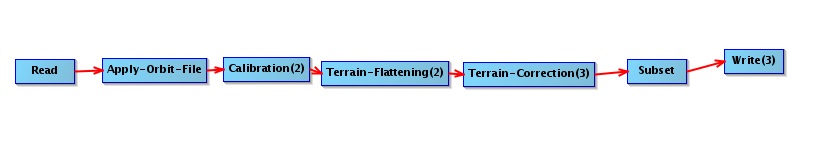
I can create my DEM files “snapped” to this grid, but when I feed them into the s1tbx terrain correction algorithm, I end up with corners on arbitrary boundaries. For example, when I use a DEM file with these corner coordinates:

Upper Left ( 472210.000, 3118530.000) ( 32d43’0.68"E, 28d11’32.05"N)
Lower Left ( 472210.000, 2876190.000) ( 32d43’20.30"E, 26d 0’15.49"N)
Upper Right ( 762100.000, 3118530.000) ( 35d40’9.45"E, 28d 9’59.40"N)
Lower Right ( 762100.000, 2876190.000) ( 35d37’4.72"E, 25d58’51.14"N)

I end up with a terrain corrected file with these corner coordinates:
Upper Left ( 471616.552, 3118977.405) ( 32d42’38.87"E, 28d11’46.54"N)
Lower Left ( 471616.552, 2876467.397) ( 32d42’58.93"E, 26d 0’24.47"N)
Upper Right ( 763254.536, 3118977.405) ( 35d40’52.11"E, 28d10’13.10"N)
Lower Right ( 763254.536, 2876467.397) ( 35d37’46.40"E, 25d58’59.40"N)

Is there any way for the s1tbx to create outputs that are “snapped” to my regular grid? (I’d prefer to not have to resample products after they are terrain corrected).

I guess this functionality is currently missing from SNAP? If so, could it be added, please?

We use SNAP to automatically apply basic preprocessing to stacks of S1 GRD-s and we have found the geolocation accuracy between scenes to be good enough for our purposes to not require additional coregistration. Currently we still need to resample these preprocessed images to the same grid outside of SNAP (we use GDAL for this). It would be excellent news if we could avoid this additional processing step.

I submitted a pull request some weeks ago that adds the image grid alignment functionality described here and this has now been incorporated into SNAP since version 5.0.4.

This functionality is currently only accessible through the graph processing interface (GPT). Set the following parameters in the Terrain-Correction operator to use it:

<alignToStandardGrid>true</alignToStandardGrid>
<standardGridOriginX>0</standardGridOriginX>
<standardGridOriginY>0</standardGridOriginY>

The alignToStandardGrid turns this feature on/off (off by default) and the standardGridOrigin parameters specify the origin point in the output CRS that the grid will always intersect with (defaults to 0,0).

A quick demo using the output from two separate S1 images

Without aligning the image grids (the default).


With the grids aligned.

3 Likes

The alignToStandardGrid is a substantial improvement and saves additional resampling to align the images after geocoding. Thank you!
I have observed a shift in the “standard” grid over my AOI, upper left at N30 E31, when specifying the origin as 0,0 vs 30,31. Using the latter, the grid precisely aligns, so that when subset, the upper left pixel of our images is exactly N30 E31. However when using the grid origin as 0,0 there is a ~1/4 pixel offset (consistent in all images). I am using units degrees. The standard grid code you added uses double and should not be the source of this offset.

2 Likes

S1TBX 6.0.4 Terrain corrected Sentinel-1 with align to standard grid origin 0,0 produces output with arbitrary grid alignment. I have run ~80 Sentinel-1 images with the same DEM. Very few have the same grid, and all are not aligned to 0. I thought my tests over a year ago verified alignment , although precision loss around the globe from 0,0 was observed. ie. if aligned to 0 degrees, with appropriate 1 arcsec pixel size, I would also expect {close} alignment at 1, 30, 125, etc.

Sorry, are you saying alignToStandardGrid used to work but is not working any longer?

ps. putting terrain flattening and terrain correction in the same graph is probably hurting performance.