Dear all,
I want to highlight two problems that regard pixel alignment as well as DEM resampling during Terrain Correction and would be interested in the opinion and experience of others. I will try to structure my post in a way that hopefully it’s clear by the end what the problems are and which open questions remain.
Basic workflow and TC settings:
The following workflow and TC settings were used for all runs using the same SLC scene. The settings of all other nodes also stayed the same of course but are not really relevant here.
Read - TN - Orb - Cal - Deb - TC - Write
<sourceBands>Gamma0_VV,Gamma0_VH</sourceBands>
<externalDEMNoDataValue>0</externalDEMNoDataValue>
<externalDEMApplyEGM>true</externalDEMApplyEGM>
<demResamplingMethod>BILINEAR_INTERPOLATION</demResamplingMethod>
<imgResamplingMethod>BILINEAR_INTERPOLATION</imgResamplingMethod>
<pixelSpacingInMeter>10</pixelSpacingInMeter>
<pixelSpacingInDegree>0</pixelSpacingInDegree>
<mapProjection>EPSG:32632</mapProjection>
<saveDEM>true</saveDEM>
<saveLocalIncidenceAngle>true</saveLocalIncidenceAngle>
External DEM:
I have created an external DEM from SRTM 1Sec HGT tiles that were automatically downloaded by SNAP and used gdalwarp to resample the pixel spacing to 10m and the projection to EPSG 32632 using bilinear interpolation.
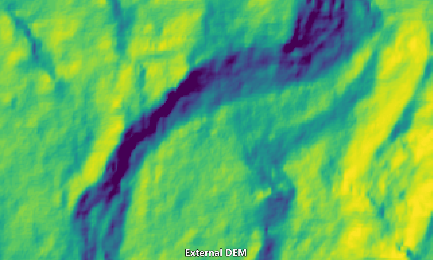
Results:
With the external DEM prepared in a way that aligns to the settings of the TC node (pixel spacing & projection), I’d assume that there is almost no difference between the external DEM and the DEM that is output by the TC node. Except for the goid correction of course, which is applied during TC.
The first comparison shows the hillshade of the external DEM (viridis) and the output DEM (greyscale) when using GAMMA and a comparable workflow. As expected there is almost no difference.

Using SNAP on the other hand produces the following result, which shows a slight shift:

This shift gets even worse when using the auto-downloaded SRTM tiles. Remember, they are also the source of the external DEM that was used in the examples above!:
Now you might ask if I have used the alignToStandardGrid and standardGridOriginX|Y parameters and if they solve the problem. I have used them and no, they unfortunately don’t solve the problem. The above results actually used 0.0 for x and y, which has been recommended in other threads before.
The pixels edges are not aligned in this case, so I have played around with this and chosen a point to align to (609775.0, 5090225.0), which lies outside of the extent of the processed scene. While this results in an alignment of pixel edges (with the external DEM used as input), there is still a shift of +1 pixel in x-dimension needed and I wasn’t able to achieve this by varying the standardGridOriginX|Y parameter.
To better understand this sparsely documented option, I have searched the forum and found this recent thread where it was described in the following way:
It aligns to an integer pixel location (floor for easting, ceil for northings)*, depending on your pixel spacing. If pixels spacing is 10, it will align to an integer increment of 10 if the values are 0.0. You can vary the alignToStandardOriginX|Y between 0 and 10, to get an offset from the integer increment of 10. If 10, you are aligned again, but the whole image will be shifted 1 pixel. Keeping it 0 seems to be the logical choice.
*adjusted based on follow-up comment
Digging a little bit deeper, I found the original thread where the pull request that implemented this option, was mentioned. This might be relevant for further dicussions.
In conclusion:
- There is a major issue with the TC node, which introduces an unnecessary shift and therefore geolocation error to the output data. I have only shown the output DEM to visualize the problem but it should be obvious that other output data like backscatter and local incident angle are influenced as well.
- I’d assume that if this problem is resolved that the alignment using the point I’ve mentioned above would also work. At least I’d hope so. Let’s say, however, that I’d still have the same problem and would only need to add a +1 pixel shift in the x-dimension to align everything properly. How would I achieve this? In theory and based on the quote above, I’d assume that this is already possible (“If 10, you are aligned again, but the whole image will be shifted 1 pixel.”). In practice this is not achievable with the current implementation of the
standardGridOriginX|Yparameter.