for Range Doppler Terrain Correction it is the best choice. For comparison in your study area, I don’t know which of the freely available ones is the most accurate.
Descending:
S1A_IW_SLC__1SDV_20190309T010839_20190309T010907_026254_02EEE4_16D7
S1A_IW_SLC__1SDV_20190414T010839_20190414T010907_026779_030232_06DF
Ascending:
S1A_IW_SLC__1SDV_20190217T131128_20190217T131158_025970_02E49F_9780
S1A_IW_SLC__1SDV_20190325T131129_20190325T131158_026495_02F7B7_184F
These are the product sir
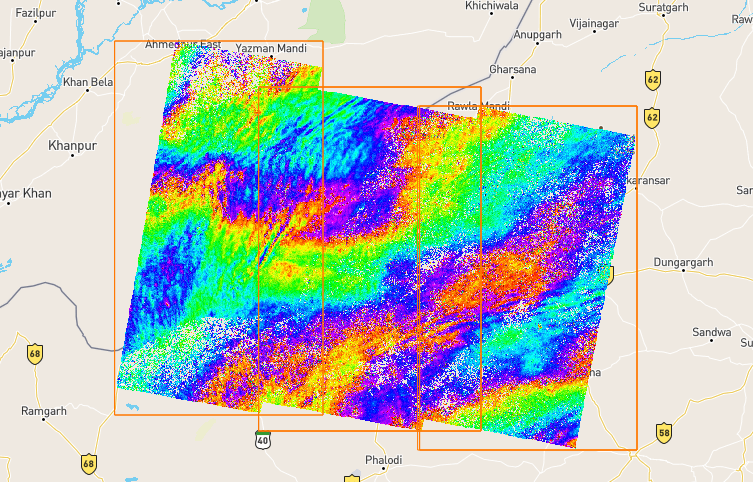
Descending (phase masked with low coherence)
Ascending (phase masked with low coherence)
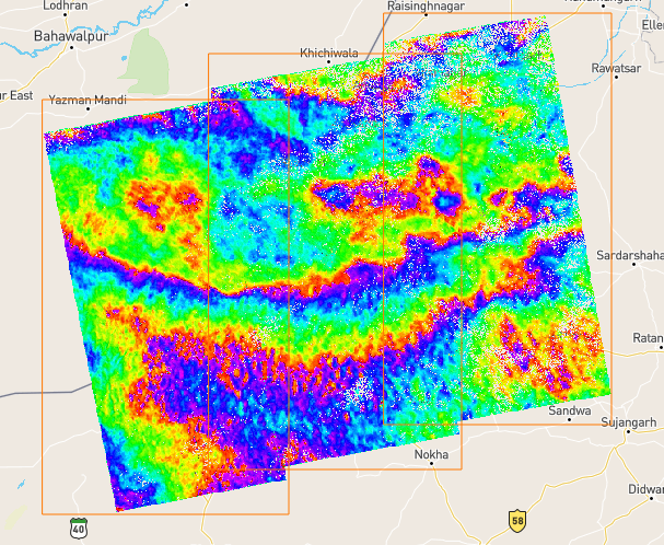
Coherence looks not bad but I miss topographic features which match in both images. Many of them look quite random and typically “wave-like”, such as in the top of descending and in the bottom of desecending interferogram. These structures are very likely caused by InSAR errors and do not represent topography.
Thankyou sir
So what should I do
I can proceed to generate DEM out of this?
As i have to fuse both passes , so will i be able to get satisfactory results after fusion?
Because mainly i have to do that and get good results from DEM fusion
you can try but based on the quality of the interferogram I have doubts that the results will be good. If you fuse two images and the quality of an area is good in one image and bad in the other, it will still be a bad fusion.
You find some good results on how interferograms should look to get usable results: The Order of DEM Creating Steps
But these are one of the very few where it really worked. You should talk to your supervisor and explain that Sentinel-1 is not a good source for DEM processing. Otherwise you might raise unrealistic expectations which you technically cannot fulfill.
Ok sir…and can you also tell me the value of Coherence you used for masking
?
And also sir . i should apply topographic phase removal in this case or not?
And i am thinking to generate DEM for 1 swath first…Because full will take time including merging etc…
If you want to extract topographic features (make a DEM) you must not apply it.
The threshold was 0.1, quite low. Testing for one swath makes sense.
oke sir…
Thankyou very much…
if any issue i will let you know once
Sir…You were not getting
Negative values with this right?
Splitting
Caliberate
Orbit file
Back-geocoding
Interferogram
Debursting
Filtering
Multilooking
Unwrapping part
phae to elevation
Geocoding
when i am doing
Multilooking
And interferogram is like:
phase info is goinginter_scrrenshot.docx (1.0 MB)
I only computed the interferogram, not the actual DEM. But the quality is the same.
The order you posted looks alright. I recomputed this with SNAP tools:
Ascending:
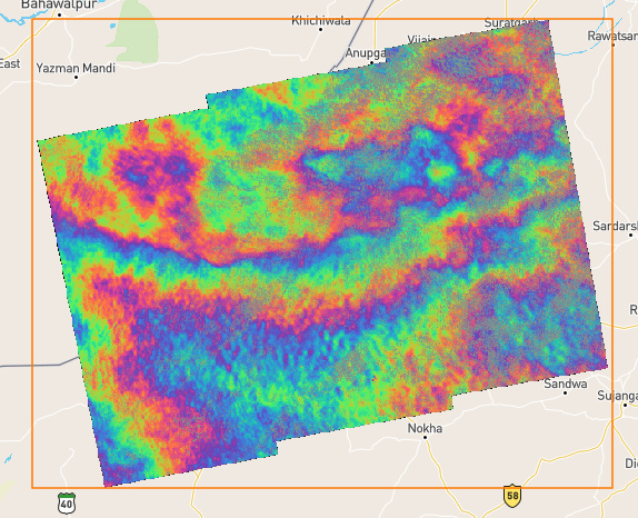
Descending
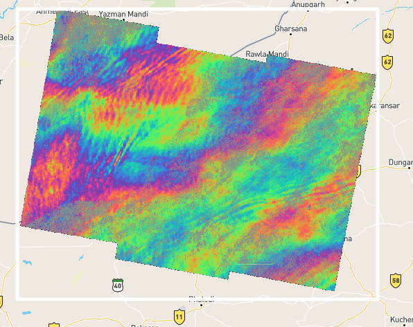
As you see, the patterns are not even the same for the area. The DEMs will be drastically different.
Ohke sir…
i am on the unwrapping part of 1 swath now, which i forgot to multilooked for descending and didnt do topophase removal
wondering!!
Drastic changes in pattern
because area i choose for both passes are almost same…with same temporal baseline
Only perpendicular baseline is 108m and 113meters for both
you can upload screenshots to share with us.
ok sir i will put for tboth
inter_scrrenshot.docx (3.8 MB)
I HOPE
now i will not GET NEgative DEM elevation values sir
otherwise it will be a big problem for me:worried:
this looks like something went wrong in the multi-looking
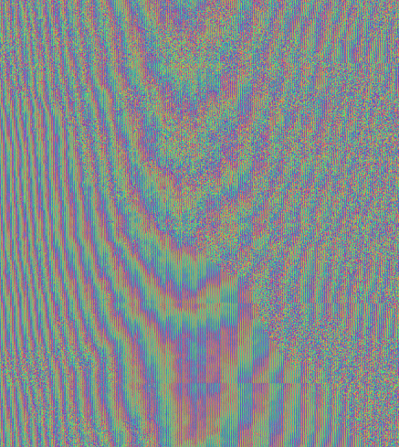
These stripes shouldn’t be there. Please check each product (after the interferogram generation) to see fafter which step they were introduced.
so i should not do multi-look then in this case
It is not a bad thing in general but it should not make your data look like this. I don’t exactly know when it happened so please carefully check each product.
