after
Stacking
Debursting
and Multilooking
After multi-look only this happened sir
after
Stacking
Debursting
and Multilooking
After multi-look only this happened sir
Doc3.docx (721.9 KB)
sir i am getting better values than previous
But some are going in negative near blue portion especially
why is it so???
because InSAR is not a perfect method. The unwrapping starts at some point and then adds up the fringes to absolute range. If the fringes are not correctly representing the topography or the coregistration produced a ramp in your interferogram, the unwrapping simply becomes too extreme. You can try unwrapping with SMOOTH instead of TOPO. But the main error occurred already in the interferogram generation.
You can try different image pairs to see if they are more suitable.
With smooth, can i getting some positive values?..
As now i have to work…
With this data only
I can’t promise that.
It is important to understand that SNAP uses an external DEM in the “phase to elevation” step to bring the unwrapped phase into a feasible range. But if the values of the unwrapped phase have a too large range, the resulting elevations will be either too large or too low.
Again, I don’t think it is fair that someone gives you the task to generate a DEM from Sentinel-1 images. Please, anyone correct me if I am seeing this wrong, but I haven’t seen one example where the quality exceeded the ones of freely available DEMs of 30 m, such as SRTM, ALOS W3D30 or ASTER…
When I tried to apply “add elevation band” to already terrain corrected image. The elevation band was not as it is intended to be. I mean it was not reprojected. what should i do now to get it same as the sigmma0 band. so that each pixel in the election band is overlayed on the same respective pixel of sigmm0 band
.it is projected in the same way, it just covers a larger extent.
You can use the layer manager to add both products to one map product (with the plus + sign > add image product)
Is their any possibility to make elevation band look same as backscatter coefficient band in terms of orientation.
the orientation is the same.
If you mean how to exclude the grey areas in the DEM, you can define a valid pixel expression in the properties of the DEM. Something like Sigma0 > 0
It depends on the use of the correct band name but this visually removes the pixels of the DEM which are not covered by radar data.
I always want to exclude the grey areas in dem(ie.the extra portion). how to make this settings default ?
or is their anyway to do thesame thing in gpt ?
you can apply logics in the band maths
IF Sigma0 > 0 THEN elevation ELSE 0
Hello sir,
As discussed previously, I generated DEM of that hilly area only of Sentinel -1 data
So
For the improvement of values, to get better DEM
after multi looking of Data
and then Applying GCPs
Will this affect the results??
most importantly, you need high coherence between both images.
If your coherence is bad, multi-looking will not improve the quality of your InSAR product.
For good coherence you need proper coregistration, rain-free acquisitions and unvegetated land.
oke sir thanks
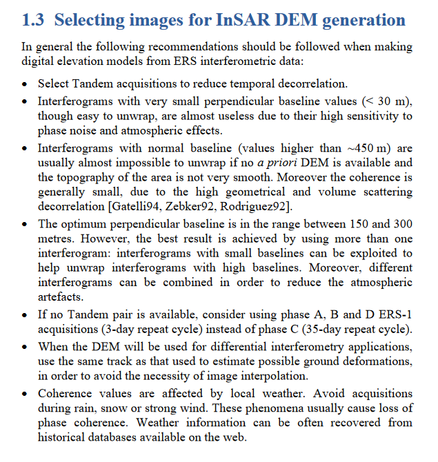
and sir can you please mention the approximate range for perpendicular baseline for 2 types of terrain .i.e. Plain terrain and undulating mountainous terrain for sentinel-1
a suitable baseline for the delineation of terrain is 150-300 meters, but there are very few Sentinel-1 pairs (with short temporal baseline) which fulfill this criterion.
Source of the document: http://www.esa.int/esapub/tm/tm19/TM-19_ptB.pdf
Personal experiment showed that about 10-15% of consecutive InSAR pairs are above 150 of perpendicular baseline (2% above 200 meters). If you have long time series, you will be able to find some good pairs. Check the perpendicular baseline in the stack overview then select appropriate pairs.
thanks for sharing this - I always wondered about the proportion.
Another good way to find image pairs with large perpendicular baselines is the ASF Baseline Tool:
good to know 
Is this in general or only related to S-1? And how did you calculate this statistics?
Of course only related to S-1. Each satellite or satellite’ constellation has its own orbital tube. For Cosmo-Skymed for example, it is common to get a perpendicular baseline greater than 1,000 meters
Very experimental. I looked at my hundreds of pairs and made a table containing among other, the perpendicular baseline. So take this info with a grain of salt