ALOS SLC L1.1 interferometry processing parameters

Hello everyone!

I have several archived ALOS PALSAR SLC L1.1 scenes provided by ESA through EO-SSO. I want to perform DInSAR for (potential) landslide detection using SNAP 6.0.5 (intel core i7, 8th generation, RAM 16GB). Deskewing was not performed. Unfortunately, the number of image acquisitions available is limited (9 images) and I encounter problems with my processing.

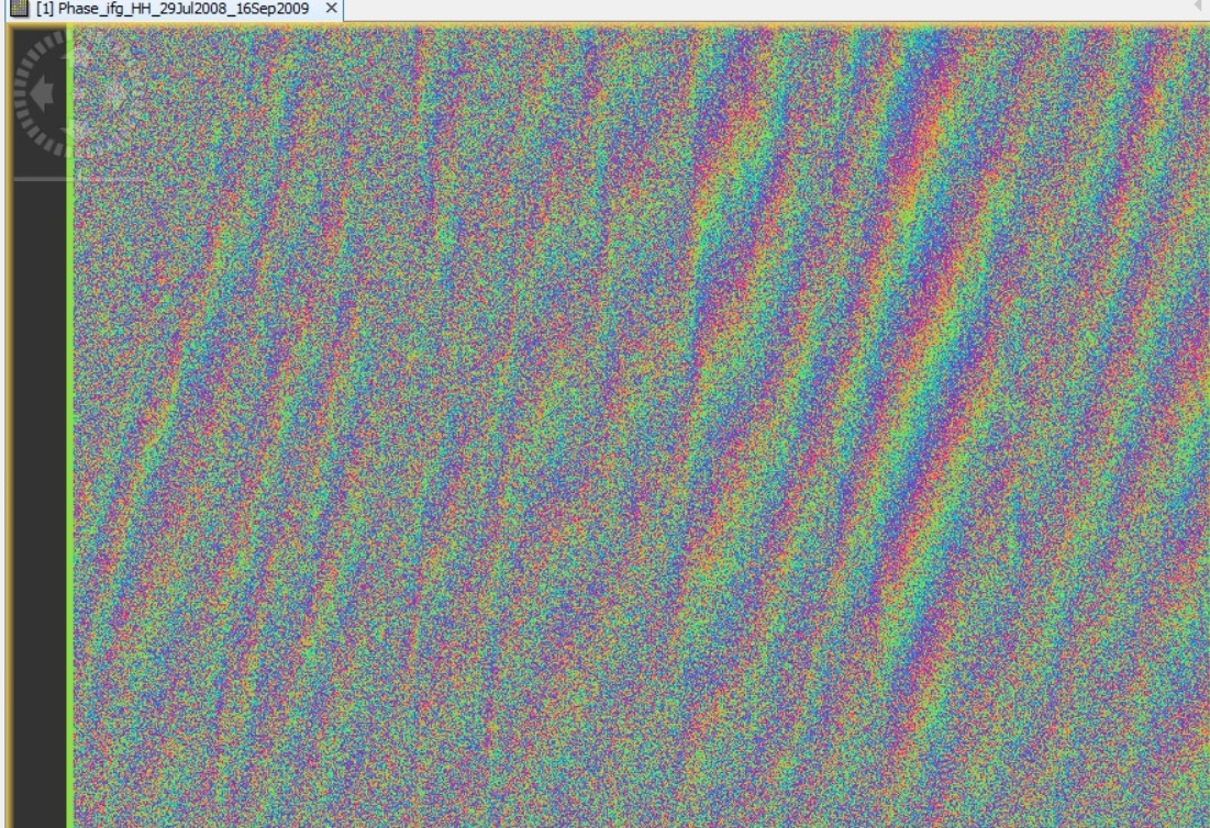
First, due to coregistration issues I came up with coherence images characterized with vertical strips as the one presented below:

The problem was overcome when resampling method in the “CreateStack” tab was selected to none instead of bicubic as I read in the forum (Problems producing interferograms with ALOS). Does anybody have any idea why this might happened? What defines the resampling type?

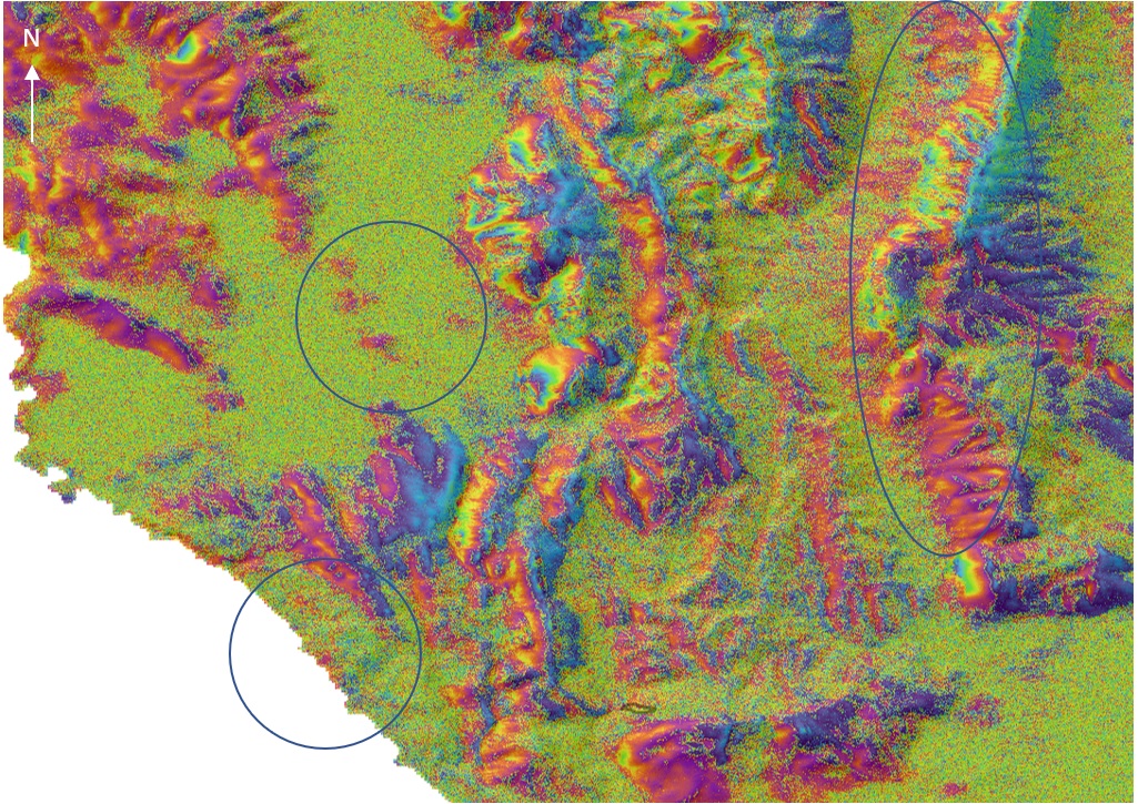
In the “flat-earth phase removal” tab (interferogram formation), there are some parameters I am not sure I fully understand. Using default parameters (degree of flat earth polynomial:5, number of flat earth estimation points:501, orbit interpolation degree:3), there were systematic phase ramps in one interferogram spanning 1-year interval:

Then I read Problem with Using ALOS Data and I used the max parameters (degree of flat earth polynomial:8, number of flat earth estimation points:1001, orbit interpolation degree:5)

The interferogram did no more present the previous trend. Would it be then wrong to use these max parameters for every pair we process? Can we only change the “orbit interpolation degree” and leave the first two parameters as default? When/how do we know that interferometric results are reliable?

Is this “orbit interpolation degree” the same with the one defined in the “topographic phase removal” tab? Does it have to be the same in these two cases?

I would really appreciate receiving any feedback with reference to that, if available!

Another thing I would like to ask is related to FBS-FBD interferometry. If FBS-FBD is not supported by SNAP, should not processing between an FBS-FBD pair be interrupted instead of coming up with interferometric results that apparently are not reliable? In case FBS-FBD is supported please let me know.

Thank you in advance!

1 Like

In some cases, these stripes were introduced by multi-looking. We discussed it here: Crop classification using SENTINEL-1A SLC data

ALOS FBS has a higher spatial resolution than FBD. I think getting correct interferograms is critical. You can try to coregister both images with FBD as master (lower resolution) and test it. Of course you need to remove the second polarization from the FBD product first (select band operator)

Thanks @ABraun for your quick response!
However, in my case, no multilooking was applied… I came up with this image after coregistering master and slave choosing resampling methor other than “none”…

And what about orbit interpolation parameters? do you have any suggestions?

maybe the resampling enhances structural inaccuracies which become visible in the coherence.
Can you try with resampling type NONE?

Yes @ABraun!
When I used resampling type NONE, coherence had no stripes. In fact, results were even better when a significant increase of GCPs number (20.000!!!) was used for coregistration.

great, good job!

Does anybody have any suggestion regarding the orbit interpolation degree issues I mentioned above?

Would it be wrong to use max parameters in the “flat-earth phase removal” tab (interferogram formation) for every pair we process e.g., (degree of flat earth polynomial:8, number of flat earth estimation points:1001, orbit interpolation degree:5)? On which basis, do we select the degree of polynomial, the number of points and the orbit interpolation degree?

Is this “orbit interpolation degree” the same with the one defined in the “topographic phase removal” tab? Does it have to be the same in these two cases?

I apologize if any inconvenience and I am looking forward to receiving any feedback.

Hello epapadak

The reason caused this phenomenon should be the baseline issue according this reply:

I test the ALOS-2 images for coseismic deformation caused at 2016/02/06 in Taiwan, result show that heighest “orbit interpolation degree” is work for ALOS-2 data, because of large perpendicular baseline I think, and get correct ground deformation.

Also, I try change “degree of flat earth polynomial” and “number of flat earth estimation points” for testing, while they don’t show any effect in my result.

For the last question, “orbit interpolation degree” should be same with the one defined in the “topographic phase removal”, because you use “that” orbit data to rebuild the topographic phase, so it should be use same “orbit interpolation degree” I think.

Cheers.

1 Like

Hello @constantinevi!

Thank you very much for your message! I could not agree more to all that you wrote :slightly_smiling_face:
Changing “degree of flat earth polynomial” and “number of flat earth estimation points” did not show any effect in my testing either.

Since this phenomenon should be related to the baseline issue, would not it be better and until this is fixed by SNAP, to use the maximum parameters (i.e., max “degree of flat earth polynomial”, max “number of flat earth estimation points” and max “orbit interpolation degree”?

Yes, though I change “orbit interpolation degree” only.

Thank you very much for your quick response @constantinevi!

Cheers

Hello again @constantinevi and everybody that might be interested in this topic,

After several tests I made, I would really appreciate receiving your feedback regarding the “orbit interpolation degree” issue discussed above and the following outcome.

Two ALOS SLC FBS scenes in ascending mode, spanning the period 13/03/2008 - 20/12/2010, and having Bperp=140m, were processed.
Differential interferograms presented below are filtered, multi-looked and terrain corrected.

Fig1. Using “degree of flat earth polynomial”=5, “number of flat earth estimation points”=501, and “orbit interpolation degree”=5

Fig.2 Using “degree of flat earth polynomial=5”, “number of flat earth estimation points”=501, “orbit interpolation degree”=3

Do you still think that the 5th “orbit interpolation degree” could be safely selected in every pair processed? Several fringes of interest (bottom and top left circles) are not highlighted in the product generated using the 5th degree. In particular, the area at the bottom, is a known slow-deforming area.
On the other hand, it seems that topography was better removed in Fig.1 (orbit int. degree=5). Do you think that the fringes observed in the mountainous area (Fig.1, within the right circle) relate to atmosphere?

Looking forward to receiving your feedback!

1 Like

Anybody any ideas/suggestions?

Of cause no. for some pairs, the setting “5” looks to be insufficient. Because of the limited of images, I can’t do more test to verify and have a clearly conclusion.

It is true … the number of images is limited to check. What I am wondering is, if the 5th degree is insufficient then the 4th degree would be insufficient as well, or not? Is there any chance that we get worse results using the 5th degree instead of using the 4th degree?

@ epapadak Could you please share your steps for SLC processing!

I had to do same thing so i was wondering if for ALOS data the processing is the same as for S1.

Hello @hriston_bg

For ALOS processing the steps differ. You may find steps and parameters used in Problems producing interferograms with ALOS

The only diffrence is that I did not deskew ALOS images because they were downloaded from ESA not ALASKA data portal.

@epapadak Thank you for this reply. I also have data from ESA, but I didn’t know that deskewing should not be applied. Could you please clarify?
I made a graph following the steps used in used in Problems producing interferograms with ALOS 1.

@hriston_bg I apologize for my late response.
After proper registration in https://eo-sso-idp.eo.esa.int/idp/umsso20/registration and downloading ALOS SLC images from EO-SSO for my AOI, I just contacted with ESA TellUS Customer service portal and ALOS PALSAR support team confirmed that I did not need to deskew the products. First time I read about not deskewing ALOS images if provided by ESA was from step forum. I just confirmed with ALOS Palsar support team of ESA.

I hope that was helpful…