Best practice to convert and reproject Sentinel-3 radiances to reflectance

I need to create an script to transform SLSTR and OLCI radiances to TOA reflectances. I’ve tried gpt but it does reproject the file to Lat/Lon. I’d need to convert to TOA reflectance and then perform the reprojection to, e.g. Sinusoidal.

My questions are:

  • What would is be the best practice to do the conversion to reflectances?, to use gpt or snappy?
  • Once the transformation is done, what would it be the best way to reproject?

Thanks in advance.
Gerardo

2 Likes

gpt can reproject to nearly any CRS. It just needs to be configured.
OLCI can be converted to TOA reflectances by the Radiance-to-Reflectances processor which is located in the menu at Optical / Preprocessing / Radiance-to-Reflectances Processor
With the release of SNAP 6 (we aim for End of June) this processor shall also support SLSTR. Currently it is not supported.
You can create a graph which contains to operators, the Rad2Refl and the Reprojection. This graph can then be invoked from the command line for several products.
To create such a graph you can either use the Graph Builder and adapt the resulting graph. You can also open the the Processors individually and use the stored configuration in you graph.

The answer to the question to either use gpt or snappy depends on your environment you use and how it fits to you other tools. But in general I would suggest gpt.

Following the steps I did to create the attached graph olci_rad2refl_reproj.xml (1.5 KB).

  1. Call gpt Rad2Refl -h to get a basic graph template. Copy the shown xml into a text file.
  2. Call gpt Reproject -h Copy only the node part and paste it into the text file.
  3. Change the nodeId of Rad2Refl-Node and use it in Reproject-Node as source.
  4. Disable the collocateWith source product.
  5. Now getting the parameter section from the GUI of the processors
    5.1 Open Rad2Refl, configure it and the copy the parameters from File / Display Parameters, replace the template parameters in the xml
    5.2 Open Reprojection, configure it and the copy the parameters from File / Display Parameters, replace the template parameters in the xml
  6. save the xml file

You can call this on the command line by

gpt olci_rad2refl_reproj.xml -t <the_target_product_file.dim> <the_source_product_file>

2 Likes

Thank you very much for the detailed reply. I use your graph as a starting point to do the transformation to TOA reflectances and the reprojection in a single step using this graph OLCI_rad2refl_reproj_to_MODIS_Sin.xml (1.8 KB).

I want to reproject to Sinusoidal and match the MODIS sinusoidal grid, for instance the h17v03 tile. I’ve got a projected output OLCI product but there is a shift as you can see in here:

My question is of the Reproject processor is able to handle the Sinusoidal projection with custom parameters as the ones used in the MODIS Sinusoidal grid?

Thanks again.

Cheers,
Gerardo

Yes you can customise the reprojection. The best is if you try it within SNAP Desktop.
If you have corresponding MODIS products, you can also try the collocate with option and specify the modis product here.

The shift might also have the reason of a shift in OLCI data. There was one in older products. And I’m not sure of the accuracy of the MODIS data.

You could try to reproject both to WGS84 separately and export to kmz file. Then compare the images with Google Earth.

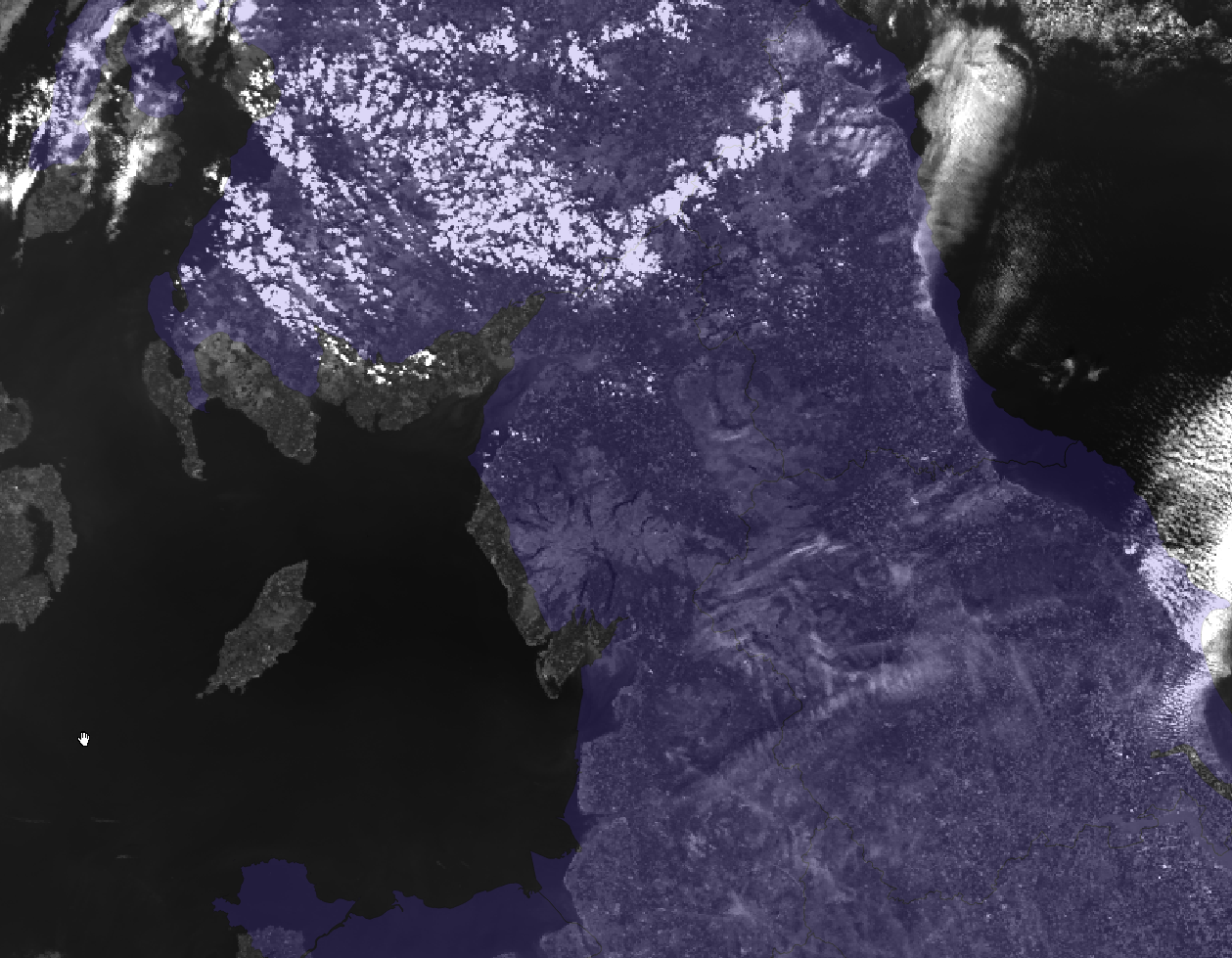
Thanks again. I tried both approaches on the latest version of OLCI data, the image is from May 11th:

  • Using the aforementioned graph with the customised Sinusoidal projection produced the image projected in Sinusoidal but using WGS84:
PROJCS["Sinusoidal",
    GEOGCS["WGS84(DD)",
        DATUM["WGS84",
            SPHEROID["WGS84",6378137.0,298.257223563]],
        PRIMEM["Greenwich",0.0],
        UNIT["degree",0.017453292519943295],
        AXIS["Geodetic longitude",EAST],
        AXIS["Geodetic latitude",NORTH]],
    PROJECTION["Sinusoidal"],
    PARAMETER["semi_major",6371007.181],
    PARAMETER["semi_minor",6371007.181],
    PARAMETER["longitude_of_center",0.0],
    PARAMETER["scale_factor",1.0],
    PARAMETER["false_easting",0.0],
    PARAMETER["false_northing",0.0],
    UNIT["Meter",1],
    AXIS["Easting",EAST],
    AXIS["Northing",NORTH]]

instead of the projection parameters I set (which are the ones used in the MODIS sinusoidal grid) :

PROJCS["unnamed",
    GEOGCS["Unknown datum based upon the custom spheroid",
        DATUM["Not specified (based on custom spheroid)",
            SPHEROID["Custom spheroid",6371007.181,0]],
        PRIMEM["Greenwich",0],
        UNIT["degree",0.0174532925199433]],
    PROJECTION["Sinusoidal"],
    PARAMETER["longitude_of_center",0],
    PARAMETER["false_easting",0],
    PARAMETER["false_northing",0],
    UNIT["Meter",1]]
  • I tried to use the UI to do the collocation but the result were different. The UI produced an output in lat/lon.

Any thoughts about what would be the issue?. Once again, what I need is to convert OLCI radiances into TOA reflectances and then reproject to march a MODIS Sinusoidal grid.

Thanks a lot for your help.

Maybe the problem is also that you use the tie-point based GeoCoding of OLCI.
You can switch to pixel based GeoCoding.


This setting is also considered when using the command line.

Hi changed the setting and both in the UI and command line and the results where even worse. Additionally, it took more than one hour to do the collocation. Anyway, any other hint to being able to do the conversion to TOA and the reprojection? – thanks!

Which MODIS data do you use?

I use the MOD09GA collection 6.

Hi, jumping onto this thread - how would I implement the radiance to reflectance conversion with snappy? Thanks, Sam

Actually this is already implemented. You just need to call

olci_refl_Product = GPF.createProduct(‘Rad2Refl’, parameters, olci_rad_Product)

Or you implement you own operator if you know a better way. You know how this can be down.

The equation is pretty simple.
it is implemented here:


Respectivly here:

Great thanks Marco

Good morning,

I seem to have a problem with implementing this conversion. I have written this sort of script:

Script

import numpy as np
import snappy
from snappy import GPF
import jpy

# 1. Open Product
s3prod = snappy.ProductIO.readProduct(product_path)

# 2. Set parameters
HashMap = jpy.get_type('java.util.HashMap')
params = HashMap()
params.put("sensor", "OLCI")
params.put("conversionMode", "RAD_TO_REFL")
params.put("copyNonSpectralBands", "false")

# 3. Run conversion
s3prod_refl = GPF.createProduct("Rad2Refl", params, s3prod)

Testing

To test this I took a test product and compared the results of my script and running the SNAP desktop implementation. I got the values as:

# Get pixel values of Oa01 band
h = s3prod_refl.getSceneRasterHeight()
w = s3prod_refl.getSceneRasterWidth()
pixel_values = np.zeros(w * h, np.float64)
obj = s3prod_refl.getBand("Oa01_reflectance")
obj.readPixels(0, 0, w, h, pixel_values)
pixel_values.shape = h, w

#Results

I seem to have some difference between the pixel values.

For example, for test product: S3A_OL_1_EFR____20161023T100950_20161023T101250_20161023T120602_0179_010_122_1979_SVL_O_NR_002.SEN3

I find things like:

  • values from my script (blocks of the same value):
    pixel_values[0, 126] = 0.4881261…
    pixel_values[0, 127] = 0.4881261…
    pixel_values[0, 128] = 0.4881261…
    pixel_values[0, 129] = 0.4881261…

  • same values from snap desktop:
    desktop values[0, 126] = 0.49819
    desktop values[0, 127] = 0.49814
    desktop values[0, 128] = 0.49809
    desktop values[0, 129] = 0.49804

Any ideas what could be the problem here?

Thanks,

Sam

Can you test something for me, Sam?

Please copy the file
C:\Users\<User_Home>\AppData\Roaming\SNAP\modules\org-esa-s3tbx-s3tbx-rad2refl.jar
to <INSTALL_DIR>\snap\modules\ and replace the existing one. Maybe you create a backup of this file first.

If I’m right the values will be the same as in the desktop.
I fear that the updates are not correctly considered by snappy. And that it is not deterministic which version is used.

Do you mean:
C:\Users\<User_Home>\AppData\Roaming\SNAP\modules\org-esa-s3tbx-s3tbx-rad2refl.jar
to <INSTALL_DIR>\s3tbx\modules where the existing copy is?

If I put it in s3tbx\modules now on the line:
obj.readPixels(0, 0, w, h, pixel_values)

get the error:
RuntimeError: java.lang.RuntimeException: Cannot construct DataBuffer.

EDIT: Correction this now seems to work!

Ahm yeah, in the INSTALL_DIR it is in the s3tbx directory. You’re right.

That it now works is not good news. But I expected it. This means that modules updates are not considered by snappy. Or at least not correct. It might be random from run to run which module is used. Either the old 5.0 module or the latest module e.g. 5.0.7. This means snappy is not reliable.

I consider this as critical issue for the next release.

Okay, thanks for the information Marco. Will await the future release

FYI after testing this doesn’t seem to be a problem in the linux installation of snap and snappy. Best, A.

Thanks for this info.
Did you try several times? because it can happen that it sometimes works and sometimes not.
Actually there should be no difference between Windows and Linux.

Marco,

In the end I managed to create a graph to convert OLCI TOA radiances to TOA reflectances using a graph. As you suggested I used the per-pixel geocoding instead if the tie-points, therefore I’ve got the full size latitude and longitude bands. Now I need additional information at full resolution, for instance, the view and Sun angles, I need per-pixel data, as in the latitude and longitude bands.

I checked the full resolution latitude and longitude and the tie-point and the interpolation it doesn’t seem to be linear, is it?. My question is, how do you create the full resolution bands from the tie-point bands?

Thanks again for your help.

Gerardo