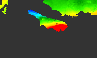
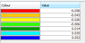
no, this is not mandatory. If you manually calculate the displacement, you just need to define a reference height later to define where is zero displacement in your raster.
Thanks… where I can define the the reference height in the raster, please? specifically on which product…
Thanks Again Mr ABraun:grinning:


in the band maths, please see here:
Ok thanks I understand, but where I shall start to do this procedure? I do not know as I am new user of SNAP. Do you have any guidelines or steps to do so, if so, please forward it to me… With regards
At which point do you struggle?
InSAR is not the easiest technique to start with. Did you see the SNAP tutorials?
http://step.esa.int/main/doc/tutorials/
ASF also offers great ones:
https://www.asf.alaska.edu/asf-tutorials/sar-and-insar-guides/
ESA provides excellent materials on the theories behind it: http://www.esa.int/About_Us/ESA_Publications/InSAR_Principles_Guidelines_for_SAR_Interferometry_Processing_and_Interpretation_br_ESA_TM-19
I know InSAR techniques but I never used the SNAP! I mean the step of Selecting a good stable point in SNAP software? I hope you understand my point… I am so sorry If I bothered you with my questions ?
SNAP cannot do this for you, this is simply a step of logic. If you derive deformation with the equation named above (using the incidence angle), you get a raster showing the relative displacement between both dates. It has no absolute meaning unless you subtract that number from the whole raster.
I tried to explain it here: Subsidence map in 3d view
So, my question is, how I do that subtraction you mentioned earlier from the whole raster unwrapped phase map, please? can you show me that by taking a screenshot in SNAP software? I do really appreciate your help with me
Many thanks Dear ABraun ![]()
First you derive the displacement from the unwrapped phase, either with the module “phase to displacement” or manually entering the equation on the band maths. If the latter is the case, you need to reference it to zero displacement manually.
Please simply read the first couple of posts in this topic, everything is explained there already very well:
A tutorial is given here: Proccessing SAR images - #14 by ABraun
Please also read the notes two posts below, some parts of the tutorial are outdated and no longer required with the current version of SNAP.
Many thanks for your assistance. I will follow the topics you have sent it to me… I do not know how to thank you Dear ABraun!
Dear ABraun, I have successfully reached the deformation map of my interest area that we have been discussing on it from last week.
I wonder how I can get all the data (latitude, longitude along with uplift and downlift/cm ) in a text file or excel file? is there any way to import such thing to GIS software in order to classify the data and do some analysis
Many thanks
I have found the same topic you are talking about it our nice forum, I will follow it
Thanks
you apply Terrain Correction on your data (you can include lat/lon bands) and then you can open the img files in the data folder in any GIS.
Alternatively, you can place pins at significant locations and export them (including coordinates and the LOS subsidence) with the Pin Manager, as demonstrated here: Export values from Sentinel 2
The final product should be vertical displacement not LOS! isn’t it?
I have applied the equation as you sated before, (Unw_Phase * wavelength in mm) / (-4 * PI * cos(rad(incident_angle))
I am I right? Thanks
according to my understanding, the equation is just approximating the vertical elevation change. In fact, it is still largely representing the change of surfaces along the line of sight. There is no simple way retrieving it from a single InSAR image pair (confirmed by mengdahl here). johngan nicely explained the difference here.
A comparison between the formula and the phase to displacement module is given here - they are nearly the same.
This was discussed this in several topics:
- Difference between vertical and LOS displacement
- Vertical displacement senitnel 1 interpretation
- Vertical and horizontal displacement
- The phase shift originates from horizontal or vertical displacements
Two posts naming formulas:
Hi. Can I ask how vertical displacement interprets? Is the line of sight direction considered in this situation? This is my unwrapped vertical displacement (vv) result.


Greetings Braun!
I want to ask you about the formula. Are there any references that certify the reliability of the results that they are produced from this formula?
Thank you in advance 
the formula itself is good, but what matters is the quality unwrapped phase
But there are numerous approaches to get vertical displacement copmponents:
how to change displacement unit from meters to milimeters?
help me, i want to change it
One thing I am struggling with, the interferogram and the unwrapped phase have relative values which needs to be referenced based on a location where no displacement has occured.
To what are the wrapped/unwrapped or LOS displacement values relative to?
How come would a pixel have 25 mm relative los displacement value while the target represented by that pixel hasn’t moved at all during the interval between the acquisition?