I did a few tests because I still wonder about the best pre-processing parameters for Sentinel-1.
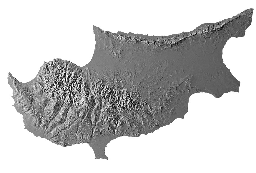
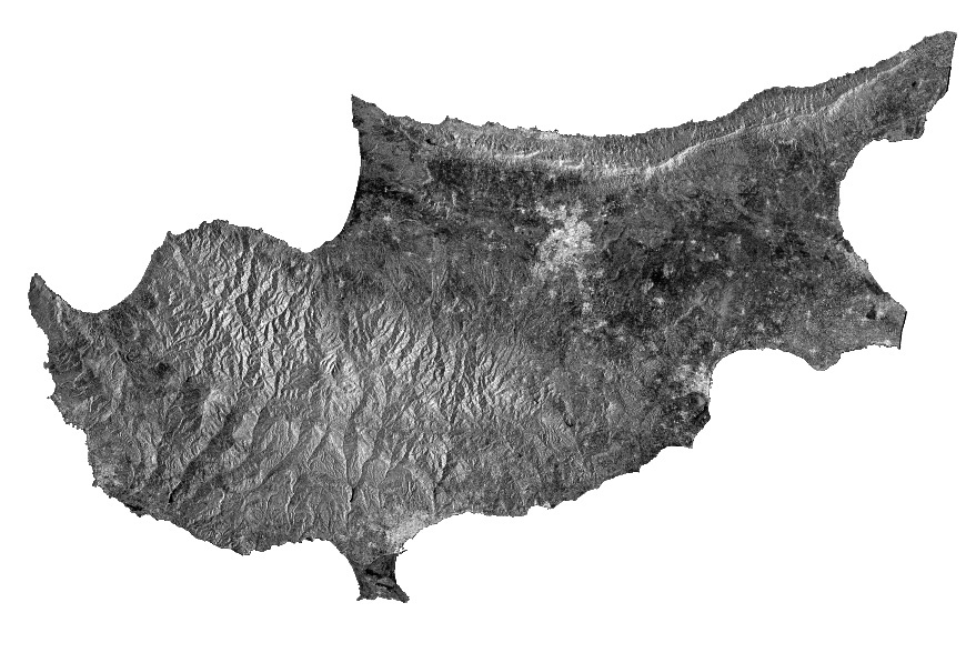
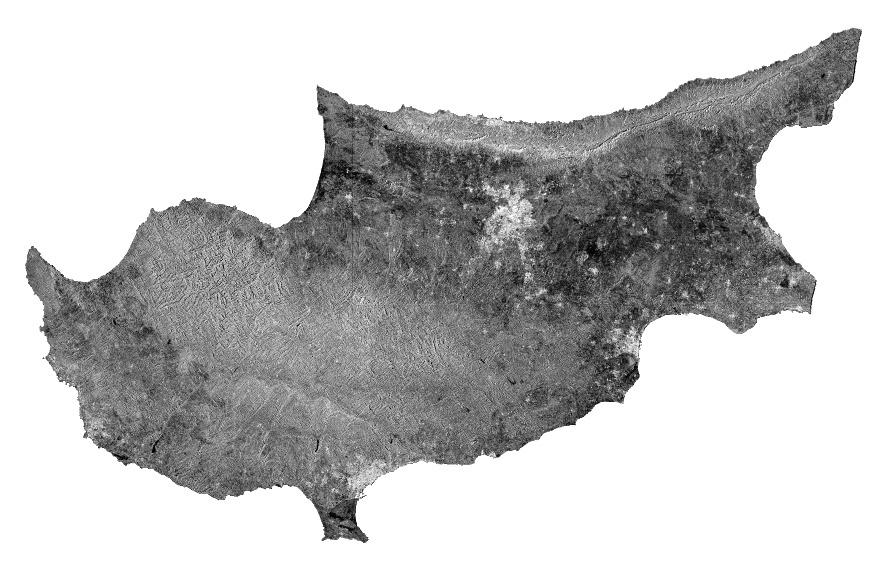
I therefore downloaded a Scene from 12.09.2016 which covers Cyprus (GRD and SLC). I chose this area due to its topographic complexity and the little vegetation cover.
These are the results:
You can compare them best when you download them and skip through them (by Windows Preview/Slideshow, for example) radiometricCorrection.zip (1.8 MB)
Does radiometric normalization in the RD Terrain Correction module replace/substitute Calibration? You can’t apply both. The result is however the very same.
Shouldn’t actually Terrain Flattening somehow replace the topographic/radiometric normalization? The first relies on the illuminated area and the second relies on the incidence angle (see a nice comparison here)
Why are there slight differences between terrain flattened SLC and GRD data?
Andreas, thanks for the comparison. Indeed the terrain flattening should replace the radiometric normalization. The normalization has been there since NEST. I’m not sure if there is any advantage to leave in the software multiple ways of doing similar things with new methods added in over time. I suppose each user could determine which works best for their particular scenario and data.
However, if something is clearly replaced by a better method then we should remove the obsolete method.
I believe it’s true you’ll get a similar results for S1 and RS2 because they use an LUT. There is an open issue to address this. Basically the local incidence angle isn’t being used for S1. It may make more sense to disable the normalization for S1 until the issue is addressed.
Hello,I have a question that I don’t know how to get the “Incidence Angle Image” by the snap just like your showing above .can you tell me how to get the Incidence Angle Image,and what tools I should be use.
thank you
@ABraun I am still confused, I have followed the following steps
GRD image - thermal noise removal- apply orbit file - calibration - filter- terrain correction
If you have already calibrated then no you don’t need the normalization in terrain correction. Normalization is essentially calibration with the local incidence angle.
Shouldn’t actually Terrain Flattening somehow replace the topographic/radiomatric normalization? The first relies on the illuminated area and the second relies on the incidence angle
The flattening just does radiometric corrections in radar geometry. Afterwards, if you want your result in map geometry, you just have to perform orthorectification (range-Doppler terrain-geocoding) to place those flattened backscatter estimates into the same map geometry as your DEM.